Installation Notes: Install the 6-M element-mounting brackets on the 17/12-M feed-
point screws, then reinstall the coax harness on top of the bracket. Install the 90-degree
element brackets onto the insulating plates with ½” screws, then loosen the worm
clamps at EB/ED and secure the insulator plates as shown. To install element tube DD,
insert the slotted end through the insulating plate and secure the opposite end to the
mounting bracket using 3/4” screws. Then, insert end-tube DE 4 inches into DD, secure
it with a worm clamp, and install the plastic end cap. Repeat the same procedure for
assembling the other leg of the element.
Step-10. Install the Six-Meter Reflector Element using the parts listed below:
[ ] 1 Element Tube, 7/16” OD x 72", slotted ends, drilled center (20-MA6B-EG)
[ ] 2 Element Tube, 3/8" OD x 28" (20-MA6B-EH)
[ ] 1 Insulator Plate, ¼” x 2-1/2” x 3-1/2”
[ ] 1 “L” bracket (attaches insulator plate to U-bolt assembly)
[ ] 1 2-3/4” U-bolt assembly with tube clamp and ¼ – 20 hardware
[ ] 2 X-hat Half-washer
[ ] 2 3/8" Plastic end cap
[ ] 4 #8 Lock washer
[ ] 4 8-32 Nut
[ ] 2 1-1/8" x 8-32 Screw
[ ] 2 1/2” x 8-32 Screw
[ ] 2 Worm clamp, 7/16”
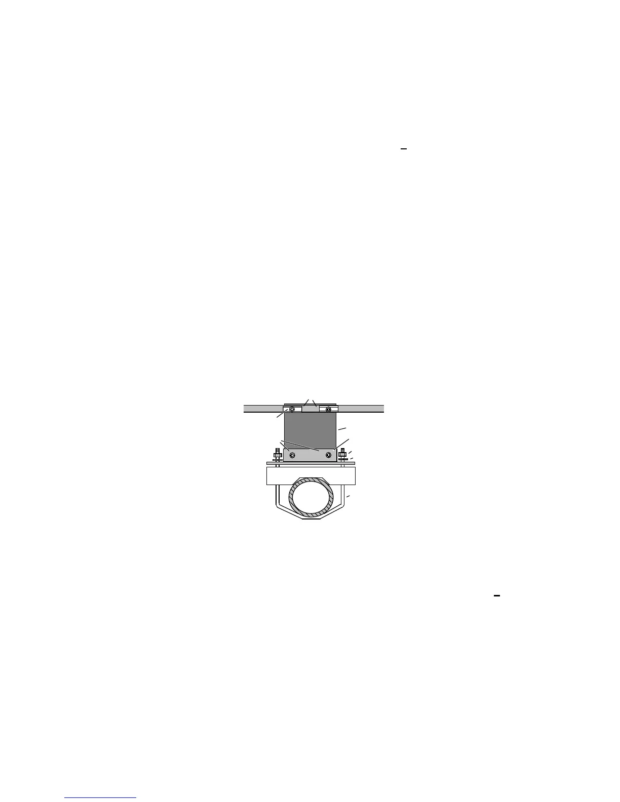
Six-Meter Reflector Assembly Diagram
1/4"-20 Nut (2)
1/4" Lockwasher (2)
Tube Clamp
Half washer (2)
Boom
MA6B
U-bolt
8-32 x 1/2" (2)
Reflector Element
Insulator Plate
8-32 x 1-1/8"
"L" bracket
Installation Notes: Assemble the reflector mounting hardware as shown in the
assembly drawing above. Use 1/2-inch screws to fasten the insulator plate to the “L”
bracket, and 1-1/8 inch screws to install the center tube of the reflector element. The “L”
bracket installs on top of the tube clamp. Position the tube clamp so the reflector will be
spaced 43” from the 6-meter driven element and tighten in place. Insert tubes EH 5
inches into each end of EG, secure with a worm clamp, and install end caps. Double-
check all dimensions against the set-up diagram below and correct as needed.