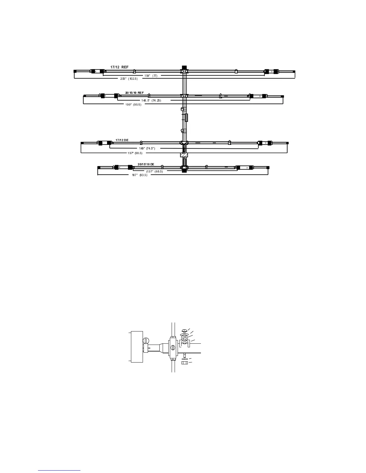
Element-Length Diagram
Step-7. Install X-hats on the HF elements: To avoid damaging the X-hat rods, the
antenna must be elevated on saw horses or similar supports. Install X-hats using the
components listed below:
[ ] 16 41" X-hat rod
[ ] 8 26" X-hat rod
[ ] 2 24" X-hat rod
[ ] 26 X-hat Half-washer
[ ] 26 X-hat Element brackets
[ ] 26 #8 Lock washer
[ ] 26 8-32 Nut
[ ] 16 8-32 x 2" Screw
[ ] 10 8-32 x 1-3/4" Screw
X-Hat Installation Detail
8-32 x 2" Screw
Half washer
X-Hat rod (41")
Element Bracket
Element (EB)
#8 Lock Washer
8-32 Nut
Trap
X-Hat Installation Notes: Each X-hat rod is secured to its element as shown in the
installation diagram above. All 41" rods are installed on 1" tubes using 8-32 x 2" screws
and the 26" and 24" rods are installed on 7/8" tubes using 1-3/4" screws. Loosen worm
clamps and align the rods so they all form an "X" pattern when sighting down the length
of the element. Then, tighten all hardware securely. Rod locations are shown in the
placement diagram below: