BASIC OPERATION
1. Power Switch Used as the master on/ off switch for equipment connected to the battery power supplied outlets.
2. MUTE Button The button can be used to mute battery mode alerts and to set up the sensitivity. For more information, please refer to the”
Function Setup Guide” section.
• Pressing the button will turn off / on the battery mode alarm, including on battery / low battery warnings.
• To turn the alarm off, press the MUTE button. You will hear two short beeps when the alarm is turned off.
• To turn the alarm back on, press the MUTE button. You will hear a short beep when the alarm is turned on.
3. LED Indicators The LEDs indicators show the UPS status, including On-Line / On Battery / AVR and Overload.
4. Battery and Surge Protected Outlets
The UPS has five battery-powered/surge suppression outlets for connected equipment to ensure the temporary uninterrupted operation of your
equipment during a
power failure. (DO NOT plug a laser printer, paper shredder, copier, space heater, vacuum, sump pump, or other large electrical devices into the
“Battery and Surge Protected Outlets”. The power demands of these devices may overload and damage the unit.)
5. Full-Time Surge Protection Outlets The UPS has five surge suppression outlets.
6. Circuit Breaker Located on the back of the UPS, the circuit breaker serves to provide overload and fault protection.
7. Wiring Fault Indicator (red) This LED indicator will illuminate to warn the user that a wiring problem exists, such as bad ground, missing ground, or
reversed wiring. If this is illuminated, disconnect all electrical equipment from the outlet and have an electrician verify the outlet is properly wired. The
UPS will not provide surge protection without being plugged into a grounded and properly wired wall outlet. 8. USB Port to PC The USB communication
port allows communication between the US B port on the computer and the UPS unit. DB9 Port This port is used for connecting between the UPS and
equipment designed
to operate with dry contact closure.
8. Coax/Cable/DSS Surge Protection The Coax/Cable/DSS protection ports will protect any cable modem, CATV converter, or DSS receiver.
9. communication Protection Ports, bi-directional, will protect a 10/100/1000 Ethernet connection (RJ45).
10. Widely-Spaced Outlets Designed for AC Adapters The unit has two outlets spaced to allow AC power adapter blocks to be plugged into the UPS
without blocking adjacent outlets.
REPLACING THE BATTERY
Replacement of batteries located in an OPERATOR ACCESS AREA
1. When replacing batteries, replace with the same number of the following battery: CyberPower / RB1270X2C for the CP900AVR / CP1200AVR and
CyberPower / RB1290X2 for CP1500AVRT.
2. CAUTION! Risk of Energy Hazard, 24 V, maximum 7 Ampere-hour battery for CP900/1200AVR, maximum 9 Ampere-hour battery for CP1500AVRT.
Before replacing batteries, remove conductive jewelry such as chains, wristwatches, and rings. High energy conducted through these materials could
cause severe
burns.
3. CAUTION! Do not dispose of batteries in a fire. The batteries may explode
4. CAUTION! Do not open or mutilate batteries. Released material is harmful to the skin and eyes. It may be toxic.
5. CAUTION! A battery can present a risk of electrical shock and a high short circuit current. The following precautions should be observed when working
on
batteries:
1) Remove watches rings or other metal objects.
2) Use tools with insulated handles.
CAUTION – RISK OF EXPLOSION IF BATTERY IS REPLACED BY AN INCORRECT TYPE. DISPOSE OF USED BATTERIES ACCORDING TO LOCAL
REGULATIONS
REMINDER: Batteries are considered HAZARDOUS WASTE and must be disposed of properly. Most retailers that sell lead-acid batteries collect used
batteries for recycling, as required by local regulations.
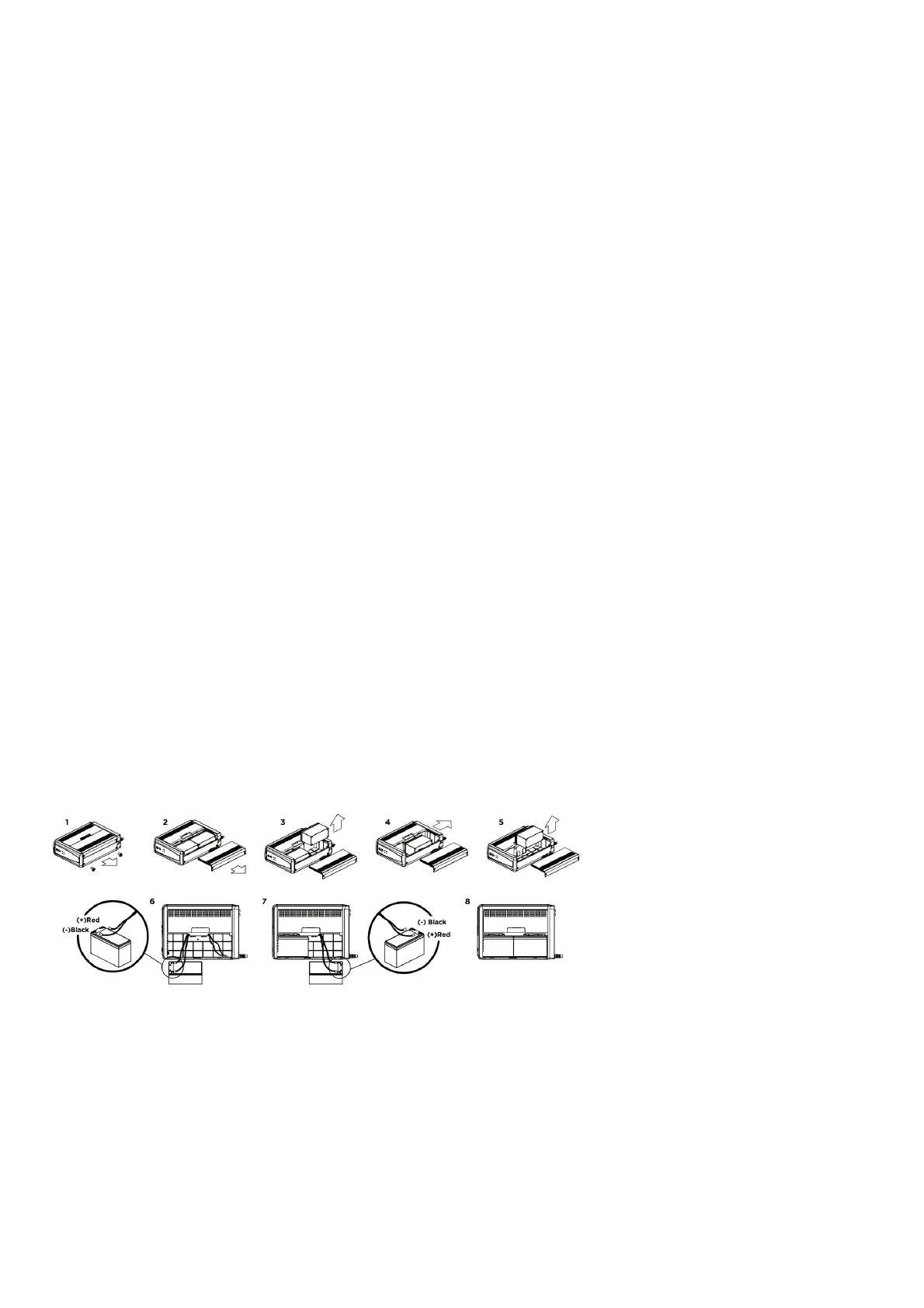
Yellow Wire to (+) Red Connector Black Wire to (-) Black Connector
Red Wire to (+) Red Connector Yellow Wire to (-) Black Connector
BATTERY REPLACEMENT PROCEDURE
1. Turn off and unplug all connected equipment.
2. Turn the UPS off and unplug it from the AC power source.
3. Turn the UPS on its side on a solid surface.
4. Remove two retaining screws located on the bottom of the UPS.
5. Press on the locking latch and slide the battery compartment cover.
6. Disconnect the battery wires from the right side of the battery and then take them out of the battery compartment.
7. Disconnect the battery wires from the remaining battery.
8. Slide the remaining battery from left to right and remove it from the compartment.
9. Install the “left side” replacement battery by connecting the yellow wire (+) to the red connector from the battery and the black wire (-) to the black
connector from the battery. Place the battery into the left side of the compartment.
10. Install the “right side” replacement battery by connecting the red wire (+) to the red connector from the battery and the yellow wire (-) to the black
 Loading...