Document No. 002-14949 Rev. *E Page 89 of 113
16.3 2.5V LDO (BTLDO2P5)
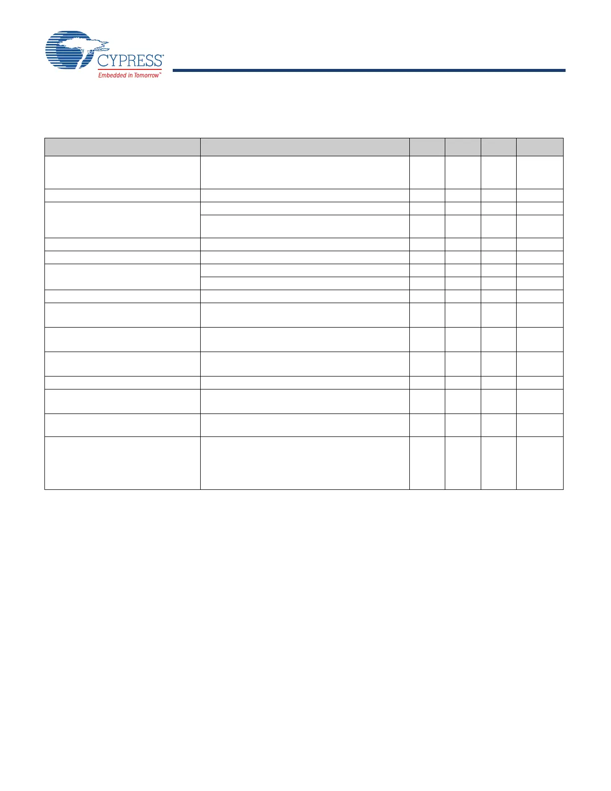
Table 39. BTLDO2P5 Specifications
Specification Notes Min. Typ. Max. Units
Input supply voltage Min. = 2.5V + 0.2V = 2.7V.
Dropout voltage requirement must be met under
maximum load for performance specifications.
3.0
3.6
4.8
1
1. The maximum continuous voltage is 4.8V. Voltage transients up to 6.0V (for up to 10 seconds), cumulative duration over the lifetime of the device, are
allowed. Voltage transients as high as 5.0V (for up to 250 seconds), cumulative duration over the lifetime of the device, are allowed.
V
Nominal output voltage Default = 2.5V. – 2.5 – V
Output voltage programmability Range 2.2 2.5 2.8 V
Accuracy at any step (including line/load regulation), load
> 0.1 mA.
–5–5%
Dropout voltage At maximum load. – – 200 mV
Output current – 0.1 – 70 mA
Quiescent current No load. – 8 16 µA
Maximum load at 70 mA. – 660 700 µA
Leakage current Power-down mode. – 1.5 5 A
Line regulation V
in
from (V
o
+ 0.2V) to 4.8V,
maximum load.
––3.5mV/V
Load regulation Load from 1 mA to 70 mA,
V
in
= 3.6V.
––0.3mV/mA
PSRR V
in
V
o
+ 0.2V, V
o
= 2.5V, C
o
= 2.2 µF,
maximum load, 100 Hz to 100 kHz.
20––dB
LDO turn-on time Chip already powered up. – – 150 µs
In-rush current V
in
= V
o
+ 0.15V to 4.8V, C
o
= 2.2 µF,
No load.
– – 250 mA
External output capacitor, C
o
Ceramic, X5R, 0402,
(ESR: 5–240 m), ±10%, 10V
0.7
2
2. The minimum value refers to the residual capacitor value after taking into account part-to-part tolerance, DC-bias, temperature, and aging.
2.2
2.64
µF
External input capacitor For SR_VDDBATA5V pin (shared with Bandgap)
ceramic, X5R, 0402,
(ESR: 30–200 m), ±10%, 10V.
Not needed if sharing VBAT 4.7 µF capacitor with
SR_VDDBATP5V.
–4.7
–
µF


 To Next Page