22
There are many different ty pes of intercom s available on the market today .
The wiring of these intercoms can vary in some way s, but the general wiring is the same. The three main ty pes of intercom
are as follows:-
220 volt. This ty pe normally plugs into the house mains, (220 volt supply) Four wires are used on this sy stem. Two wires
go to the gate station and two wires go to the motor (trigger).
12 volt. This ty pe normally gets its power from the m otor (12 v/dc). This means that a m inimum of six wires are needed to
run from the handset. Two wires to the gate station and four wires to the m otor.
6 volt. This ty pe is battery operated, norm ally using 4 x “AA” ty pe batteries for power. Only four wires are needed to run
from the handset. Two wires to the gate station and two wires to the m otor (trigger)
The mounting of the intercom is the same with each type. The handset is placed inside the house / office and the gate sta-
tion is placed at the point of entry, this is normally at the gate. The gate station is normally m ounted by means of a
“gooseneck”
It is important to note that the communication cable MUST be run in a conduit.
DO NOT run communication cable in the same conduit as any 220 v cable.
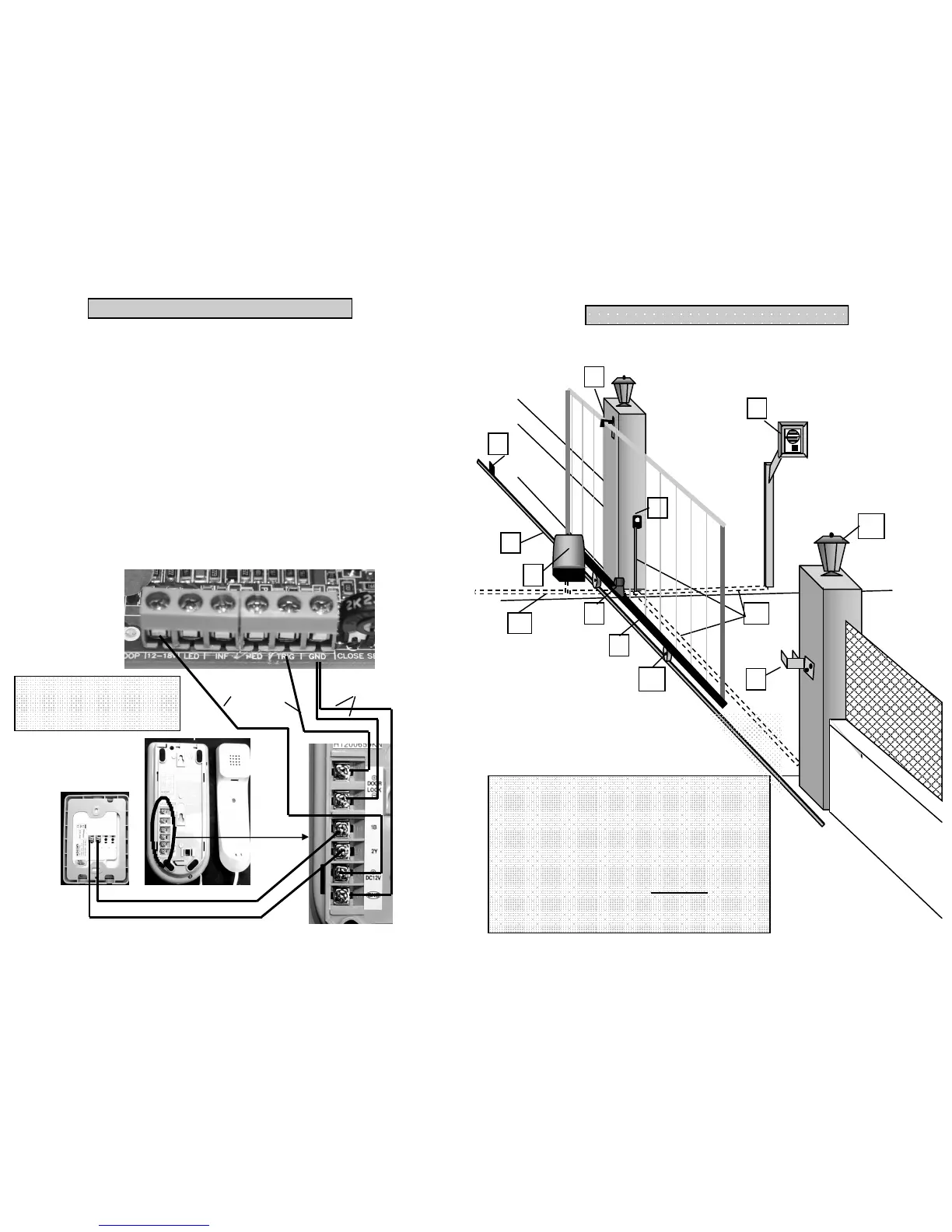
Diagram shows a ty pical Kocom 12 volt
one to one intercom sy stem . Other brands
may vary in the layout of the connector
screws.
To GND
TO TRIG
TO 12 V
CONNECTING AN INTERCOM (OPTIONAL)
7
10
1
5
8
7
6
3
4
2
9
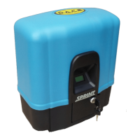
1. End stop minimum 70mm high
2. Anti-lift device / rollers.
3. Rail.
4. Compact m otor.
5. Magnet. (Compact 500 ONLY)
6. Rack.
7. Goose neck with intercom gate station. (Optional.)
8. Catch bracket.
9. DuraOptic Infra-red safety beams. (Optional.)
10. 80mm wheels.
11. Conduit carrying electrical cables. 12-16volts only
12. Pillar courtesy lights. (Optional)
The diagram below shows a basic site layout. Some items shown are optional extras. It should be noted that infra-red
safety beams are strongly recommended on all sites
11
11
12
GENERAL SITE LAYOUT