8
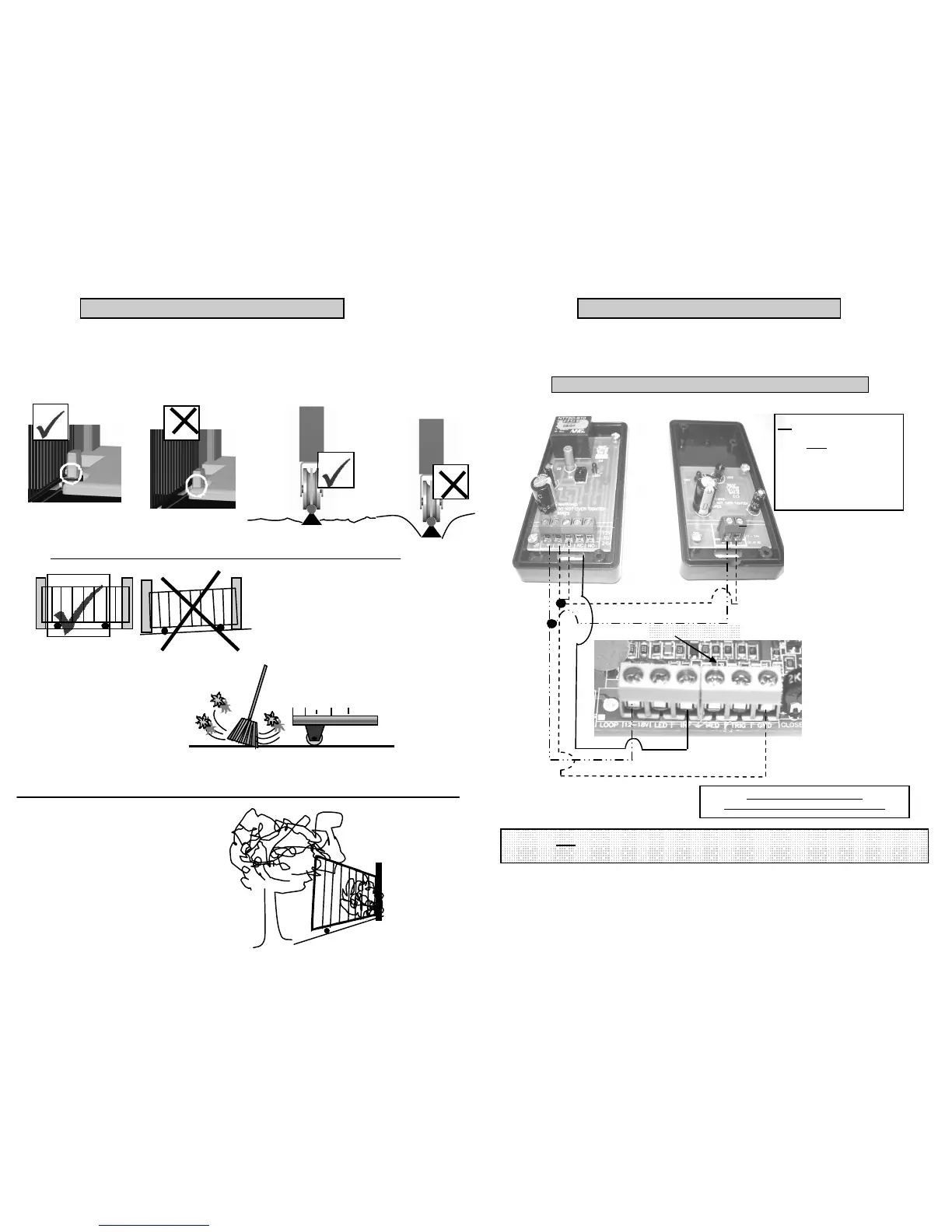
The site should be evaluated before the installation begins. The following items should be checked.
1. Flood level. The motor should be above flood level to avoid any damage to the m otor.
2. The rail must be level and should be above ground level, this will assist with keeping debris out of the path of the
wheels. Any debris ly ing on the rail may cause the motor to over current or blow a fuse.
3. Trees and growth. Any over grown trees and bushes should be cleared to allow the gate to operate sm oothly .
Mount the motor above the flood
level or a flood proof wall must be built in order to retain
any water from entering the motor
The gate must not move on its own when left in any position along the rail, if this does occur, the rail must be leveled
before the gate is automated.
Ensure that the rail is kept clear of all debris as failure to do so may lead to the gate jamming . This may lead
to motor over-current or blowing fuses.
The rail should be above ground level.
SITE EVALUATION
Keep all trees, branches, bushes and other growth clear of
the gate. Failure to do this may lead to the gate jamming.
21
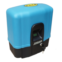
All auxiliary equipment should be connected with caution as an incorrect connection could lead to the P.C.Board
being damaged. Consult the wiring diagrams below. All power should be rem oved from the P.C.Board. before any
connections are m ade.
WIRING DURATRONIC INFRA-RED B EAMS (RECOMMENDED)
INF JUMPER on the main PCB
To be removed before beams are connected.
MAIN P.C.BOARD
NB Beams shown with front
covers removed.
Covers must be in place when
beams are active. Ensure that the
correct cover is replaced onto the
correct beam . As this may cause
faulty operation if the covers are
incorrect.
12 VOLT
GROUND
Note although the installation of infra-red safety beam s does reduce the risk of the gate
striking an object while closing it does not guarantee against it.
+ - C NC
+
WIRING AUXILIARY EQ UIPMENT