24
A loop detector is a triggering device that can be placed under the ground inside the premises. The loop will
trigger the gate open when a vehicle drives over it. It is recom mended that the DuraLoop ty pe detector is used on
y our D.A.C.E motor.
For more information on the installation of the loop, see the instructions supplied with the DuraLoop.
NOTE: multi—user mode must be selected when a loop detector is used. (Dipswitch 1)
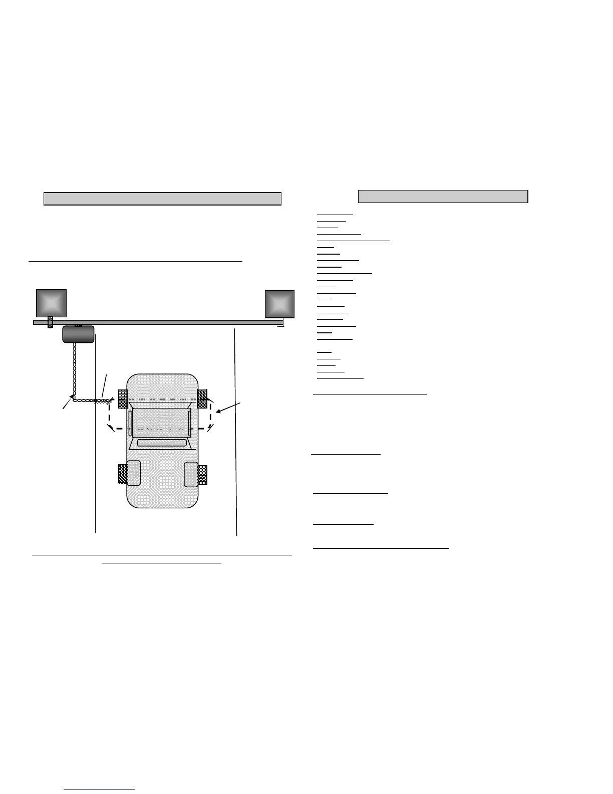
CONNECTING A LOOP DETECTOR (Optional)
Wires from the loop to the motor.
See loop manufacturers wiring
specs
Loop wires buried in driveway
Compact m otor
Slot from edge of driveway to allow for cable entry
Warning use a loop detector as a trigger only. Do not use as a safety device. Use beams
in conjunction with the loop at all times
5
TERMS AND DEFINITIONS
Anti-lift device. Stops the gate being lifted off the rail.
Auto-close. The gate will close automatically after a chosen time delay . (optional)
Battery . 12 volt 7 amp hour battery that drives the m otor.
Calibration mode. Mode the motor is in after it has been placed in m anual over-ride. (Compact 300 only )
Collision sensing / over current. In the case of a collision with an obstacle, the gate will stop.
Charger. Delivers a trickle charge to the battery .
End stop. Stops gate from running off the end of the rail and causing injury .
Foundation plate. Mechanism to anchor the motor to the ground.
Intercom. A hand set and a gate station that allows communication between the gate and the house. (optional)
Infra-red safety beams. Prevents the gate closing on an obstruction. (optional)
L.C.D. Screen. Indicates information regarding the operator status (Compact 300 only )
Magnet. Attaches to the gate to allow for accurate gate operation. (Com pact 500 only )
Manual override. Allows the gate to be moved by hand.
Motor. Gate operator.
Multi-user. Allows the gate to open and will not accept any other trigger while opening. (optional)
Party -mode. Allows the gate to remain open even when auto-close is selected. (optional)
P.C. Board. Main control board containing all the electronic com ponents.
Pedestrian m ode. Allows the gate to open partially. (optional)
Pinion. The main gear that drives the gate on the rack.
Positive close. The gate will close flush with the closed end stop / post. ( this feature is pre-set on the Compact 300
and is an option on the Compact 500 )
Rack. Length of toothed nylon gear that attaches to the gate.
Receiver. Radio receiver that receives a signal from the remote.
Remote. Hand held device that sends a radio signal to the receiver to open or close the gate.
Transformer. Reduces 220volts to 16 volts.
Test button / trigger. Button to operate the gate from the P.C. Board. Used during programm ing.
ABOUT OVER-CURRENT. When the gate is moving and it strikes an object, the software will detect the object. This will
cause the motor to stop. If the over-current is detected while the gate is closing, the gate will stop and then re-open in the
slow speed. If the over-current is detected while the gate is opening, the gate will stop and remain still. The gate will close
on the next trigger that it receives or after the auto-close time has expired. It should be noted that D.A.C.E. recommends the
use of DURATRONIC beam s on all installations to m inimise the chance of the gate closing while there is an object in its
ABOUT THE BATTERY / MAINS POWER. It should be noted that the m otor is battery operated. This m eans that the
motor will not operate with a flat battery or if the battery is removed from the m otor. The mains supply is used to charge the
battery only . The m ains will not operate the motor. In the case of a mains power failure, the battery will continue to operate
the m otor until the battery runs flat. This should be about two day s under normal conditions. The Compact 500 has two
L.E.Ds on the front of the m otor. One L.E.D. is green the other is red. The green L.E.D. m ust be on at all times, this indicates
that the m ains is on. The red L.E.D. indicates that the battery is flat.
The Compact 300 has a L.C.D. screen. The screen will show “mains fail” if the mains is disconnected.
The screen will show “low batt” if the battery is going flat.
ABOUT POSITIVE CLOSE. This means that the gate will close up against the end stop / gate post leaving no gap between
the gate and the post. This ensures that the electrical contacts of an electric fence make a solid connection when the gate is
closed. This is a pre-set function on the Compact 300. It is an optional function on the Compact 500. To set up positive close
on the Compact 500, simply program the motor with no magnet on the gate.
ABOUT AUTO-CLOSE. Auto-close can be set to m ake the gate close autom atically after a chosen time period.
It must be noted that it is dangerous and D.A.C.E. strongly advise against the setting of auto-close without the use of
DURATRONIC infra-red safety beam s.
ABOUT CALIBRATION MODE. (Compact 300 only)If the motor is placed into manual over-ride m ode. The m otor will
need to be operated 3 times after it has been re-engaged in operational mode. This is called the “Calibration m ode” NOTE this
must not be confused with program m ode. Calibration mode is done simply by operating the gate fully open and closed three
times. On the third operation the gate may go into slow m ode, this is norm al.
 Loading...