EasyManua.ls Logo

DAB e.sybox Series - User Manual

DAB e.sybox Series
54 pages
Print Icon
To Next Page IconTo Next Page
Loading...
ENGLISH
GB
57
INDEX
Key 60
Warnings 60
Responsibility 61
1.
General 61
1.1 Description of the Integrated Inverter 62
1.2
Integrated expansion vessel 62
1.3 Integrated electropump
63
1.4 Technical characteristics 64
2. Installation 65
2.1 Vertical Conguration 66
2.1.1 Hydraulic connections 66
2.1.2 Loading operation – Installation above head and below head 67
2.2 Horizontal conguration 67
2.2.1 Hydraulic connections 68
2.2.2 Orientation of the interface panel 68
2.2.3 Loading operation – Installation above head and below head 69
3. Commissioning 69
3.1 Electrical connections 69
3.2 Conguration of the integrated inverter 70
3.3 Priming 70
4. Protection systems 71
4.1 Description of blockages 71
4.1.1 “BL” AAnti Dry-Run (Protection against dry running) 71
4.1.2 Anti-Cycling (Protection against continuous cycles without utility request) 72
4.1.3 Anti-Freeze (Protection against freezing of water in the system) 72
4.1.4 “BP1” Blockage due to fault of the internal pressure sensor 72
4.1.5 PB” Blockage due to line voltage outside specications 72
4.1.6 “SC” Blockage due to short circuit between the motor phases 72
4.2 Manual reset of error conditions 73
4.3 Self-reset of error conditions 73
5. Inverter electronic control and user interface 73
5.1 Operation with control unit 73
5.1.1 Functions made available by control units 74
5.1.2 Electrical connections of utility inputs and outputs 74
5.1.3 Safety mode operation 74
5.1.4 Control unit function setup 75
5.1.5 Association and disassociation of e.sybox and control unit 75
6. The keypad and the display 76
6.1 Direct access with a combination of keys 77
6.2 Access by name with a drop-down menu 80
6.3 Structure of the menu pages 81
6.4 Blocking parameter setting by Password 82
6.5 Enabling and disabling the motor 82
7. Meaning of the individual parameters 82
7.1 User Menu 82
7.1.1 Status 82
7.1.2 RS: Rotation speed display 82
7.1.3 VP: Pressure display 82
7.1.4 VF: Flow display 82
7.1.5 PO: Absorbed power display 83
7.1.6 C1: Phase current display 83
7.1.7 Operating hours and number of starts 83
7.1.8 PI: Power histogram 83
7.1.9 Multi-pump system 83
7.1.10 Output ow meter 83
7.1.11 VE: Version display 83
7.1.12 FF: Fault log display 84
7.2 Monitor Menu 84
7.2.1 CT: Display contrast 84
7.2.2 BK: Display brightness 84
7.2.3 TK: Backlight switch-on time 84
7.2.4 LA: Language 84
7.2.5 TE: Dissipator temperature display 84
7.3 Setpoint Menu 84
7.3.1 SP: Setting the setpoint pressure 84
7.3.2 Setting the auxiliary pressures 84
7.3.2.1 P1: Setting the auxiliary setpoint 1 85
7.3.2.2 P2: Setting the auxiliary setpoint 2 85
7.3.2.3 P3: Setting the auxiliary setpoint 3 85
7.3.2.4 P4: Setting the auxiliary setpoint 4 85
7.4 Manual Menu 85
7.4.1 Status 85
7.4.2 RI: Speed setting 85
7.4.3 VP: Pressure display 86
7.4.4 VF: Flow display 86
7.4.5 PO: Absorbed power display 86
7.4.6 C1: Phase current display 86
7.4.7 RS: Rotation speed display 86
7.4.8 TE: Dissipator temperature display 86
7.5 Installer Menu 86
7.5.1 RP: Setting the pressure fall to restart 86
7.5.2 OD: Type of plant 86
7.5.3 AD: Address conguration 86
Question and Answer IconNeed help?

Do you have a question about the DAB e.sybox Series and is the answer not in the manual?

Overview

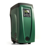
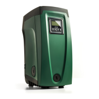
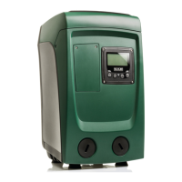
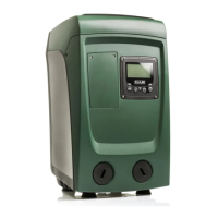
The e.sybox is an integrated system primarily composed of a self-priming multi-stage centrifugal electropump, an electronic control circuit, and an expansion vessel. It is designed for water systems supply and pressure boosting for domestic or industrial use. The device features an inverter control system that maintains a constant pressure value in delivery and ensures energy saving.

Function Description

The e.sybox automatically switches on and off based on utility needs, detecting and preventing malfunctions. The inverter varies the electropump's rotation speed to keep the hydraulic circuit pressure constant. This modulation prevents pressure drops at increased flow requests and excessively high pressures at low flow rates, optimizing energy consumption by supplying only the necessary power.

The system includes an integrated expansion vessel with a 2-liter capacity. This vessel helps maintain the system's elasticity and prevents frequent pump starts. If a flow of water is detected within 10 seconds of startup, the pump is primed and begins regular operation. If not, a priming procedure is initiated.

The e.sybox can be installed in two configurations: horizontal or vertical. The user interface panel, consisting of a display and keyboard, allows for system setup, status queries, and alarm communication. The panel can be rotated 90° for convenient reading.

The device offers various operating modes and accessory functions, configurable via input and output channels. These include constant pressure operation, set-point adjustment, pressure reduction for restart, and anti-cycling.

Important Technical Specifications

  • Electric Power Supply: 1 x 220/240 ~ VAC, 50/60 Hz
  • Maximum Current: 10 A
  • Maximum Power: 1550 W
  • Leakage Current to Earth: <2.5 [mA]
  • Overall Dimensions: 565x265x352 mm (without feet)
  • Empty Weight (excluding packaging): 24.8 kg
  • Protection Class: IP x4
  • Motor Insulation Class: F
  • Maximum Head: 65 m
  • Maximum Flow Rate: 120 l/min
  • Priming: <5 min at 8m
  • Maximum Working Pressure: 8 bar
  • Liquid Temperature Max: 40 °C
  • Environment Temperature Max: 50 °C
  • Storage Environment Temperature: -10÷60 °C
  • Constant Pressure: Yes
  • Wireless Communication: Yes
  • Protections: Dry running, antifreeze, anticycling, motor overload, abnormal supply voltages, excess temperature.

Usage Features

  • Installation: Designed for indoor use, not exposed to atmospheric agents. It operates in environments between 0°C and 50°C, provided the electrical supply is ensured (antifreeze function). Suitable for treating drinking water.
  • Hydraulic Connections: All hydraulic connections are threaded female type 1" GAS, made of brass. For vertical installation, the input is on Face F and output on Face F. For horizontal installation, input is on Face C and outputs on Face C ("OUT 1") and/or Face D ("OUT 2").
  • Loading Operation: For "above head" installations, the system is filled with clean water through the filling cap (Face F for horizontal, Face C for vertical), ensuring air is released. For "below head" installations, it loads automatically by venting trapped air through the filling cap.
  • Electrical Connections: Requires a separate electrical duct for noise immunity. The electrical connection must be in a dry place, far from flooding, and include a differential switch with IΔn ≤ 30 mA and an efficient earth system.
  • Priming: After filling and configuration, connect power with at least one utility open. If flow is detected, priming is successful. If not, the system prompts for a priming procedure.
  • Error Conditions: The system displays fault and warning indications (e.g., "BL" for water lack, "OC" for motor overload). Some errors self-reset, while others require manual intervention.
  • Control Unit Integration: Can be connected wirelessly to a remote control unit (e.g., e.sylink) for digital inputs, relay outputs, remote pressure sensing, and network communication.
  • Safety Mode: In case of communication loss or control unit error, the e.sybox switches to safety mode, indicated by a flashing icon.
  • Multi-pump Systems: Supports up to 4 e.sybox units in a pump set. Parameters can be local or sensitive (aligned across devices). The system automatically assigns addresses and determines the starting order based on working hours and inactivity.
  • Accessory Tool: A multi-function cross key is provided for removing caps, filling, and accessing the non-return valve.

Maintenance Features

  • General System Reset: Hold down all 4 keys simultaneously for 2 seconds. This is equivalent to disconnecting and reconnecting power.
  • Factory Settings Restore: Switch off the device, wait for the display to turn off, then press and hold "SET" and "+" keys while powering on until "EE" appears. This restores factory settings but requires reconfiguring system parameters.
  • Non-return Valve: The integrated non-return valve can be extracted, cleaned, or replaced if it malfunctions due to solid bodies or sand.
  • Motor Shaft: If the pump fails to start after inactivity due to calcification, the motor shaft can be manually turned using a straight tip screwdriver to free it.
  • Expansion Vessel: Air pressure in the expansion vessel should be checked and adjusted as per paragraph 1.2. The vessel can be replaced if damaged.
  • Firmware Update: Firmware can be updated between e.sybox units or via e.sylink to align versions in multi-pump systems or add new functions. Manual, automatic, and semi-automatic update procedures are available.
  • Emptying the System: Disconnect power, open delivery taps, and remove the drainage cap (Face E) to drain water.

DAB e.sybox Series Specifications

General IconGeneral
BrandDAB
Modele.sybox Series
CategoryWater System
LanguageEnglish

Related product manuals