EasyManua.ls Logo

DAB E.sybox User Manual

DAB E.sybox
54 pages
To Next Page IconTo Next Page
Page #1 background imageLoading...
Page #1 background image
ENGLISH
GB
57
INDEX
Key 60
Warnings 60
Responsibility 61
1. General 61
1.1 Description of the Integrated Inverter 62
1.2 Integrated expansion vessel 62
1.3 Integrated electropump 63
1.4 Technical characteristics 64
2. Installation 65
2.1 Vertical Conguration 65
2.1.1 Hydraulic connections 66
2.1.2 Loading operation – Installation above head and below head 67
2.2 Horizontal conguration 67
2.2.1 Hydraulic connections 68
2.2.2 Orientation of the interface panel 68
2.2.3 Loading operation – Installation above head and below head 69
3. Commissioning 69
3.1 Electrical connections 69
3.2 Conguration of the integrated inverter 70
3.3 Priming 70
4. Protection systems 71
4.1 Description of blockages 71
4.1.1 “BL” AAnti Dry-Run (Protection against dry running) 71
4.1.2 Anti-Cycling (Protection against continuous cycles without utility request) 72
4.1.3 Anti-Freeze (Protection against freezing of water in the system) 72
4.1.4 “BP1” Blockage due to fault of the internal pressure sensor 72
4.1.5 PB” Blockage due to line voltage outside specications 72
4.1.6 “SC” Blockage due to short circuit between the motor phases 72
4.2 Manual reset of error conditions 73
4.3 Self-reset of error conditions 73
5. Inverter electronic control and user interface 73
5.1 Operation with control unit 73
5.1.1 Functions made available by control units 74
5.1.2 Electrical connections of utility inputs and outputs 74
5.1.3 Safety mode operation 74
5.1.4 Control unit function setup 75
5.1.5 Association and disassociation of e.sybox and control unit 75
6. The keypad and the display 76
6.1 Direct access with a combination of keys 77
6.2 Access by name with a drop-down menu 80
6.3 Structure of the menu pages 81
6.4 Blocking parameter setting by Password 82
6.5 Enabling and disabling the motor 82
7. Meaning of the individual parameters 82
7.1 User Menu 82
7.1.1 Status 82
7.1.2 RS: Rotation speed display 82
7.1.3 VP: Pressure display 82
7.1.4 VF: Flow display 82
7.1.5 PO: Absorbed power display 83
7.1.6 C1: Phase current display 83
7.1.7 Operating hours and number of starts 83
7.1.8 PI: Power histogram 83
7.1.9 Multi-pump system 83
7.1.10 Output ow meter 83
7.1.11 VE: Version display 83
7.1.12 FF: Fault log display 83
7.2 Monitor Menu 84
7.2.1 CT: Display contrast 84
7.2.2 BK: Display brightness 84
7.2.3 TK: Backlight switch-on time 84
7.2.4 LA: Language 84
7.2.5 TE: Dissipator temperature display 84
7.3 Setpoint Menu 84
7.3.1 SP: Setting the setpoint pressure 84
7.3.2 Setting the auxiliary pressures 84
7.3.2.1 P1: Setting the auxiliary setpoint 1 85
7.3.2.2 P2: Setting the auxiliary setpoint 2 85
7.3.2.3 P3: Setting the auxiliary setpoint 3 85
7.3.2.4 P4: Setting the auxiliary setpoint 4 85
7.4 Manual Menu 85
7.4.1 Status 85
7.4.2 RI: Speed setting 85
7.4.3 VP: Pressure display 86
7.4.4 VF: Flow display 86
7.4.5 PO: Absorbed power display 86
7.4.6 C1: Phase current display 86
7.4.7 RS: Rotation speed display 86
7.4.8 TE: Dissipator temperature display 86
7.5 Installer Menu 86
7.5.1 RP: Setting the pressure fall to restart 86
7.5.2 OD: Type of plant 86
7.5.3 AD: Address conguration 86

Table of Contents

Other manuals for DAB E.sybox

Questions and Answers:

DAB E.sybox Specifications

General IconGeneral
BrandDAB
ModelE.sybox
CategoryWater Pump
LanguageEnglish

Summary

KEY

WARNINGS

Skilled personnel

Advice on installation by competent, qualified personnel with required technical qualifications.

Safety

Pumped liquids

RESPONSIBILITY

1- GENERAL

Applications

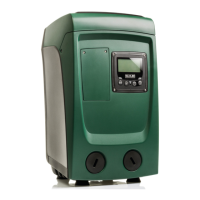
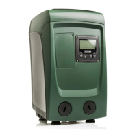
Specifies the uses of the product for water systems and pressure boosting for domestic or industrial use.

1.1 Description of the Integrated Inverter

1.2 Integrated Expansion Vessel

1.3 Integrated electropump

1.4 Technical characteristics

2- INSTALLATION

2.1 Vertical Configuration

Provides instructions and dimensions for installing the system in a vertical orientation, including connection points.

2.1.1 Hydraulic connections

2.1.2 Loading Operation

2.2 Horizontal Configuration

2.2.1 Hydraulic connections

Details hydraulic connections for horizontal installation, including dual delivery options and thread types.

2.2.2 Orientation of the Interface Panel

Explains how to orient the user interface panel for optimal viewing and readability.

2.2.3 Loading Operation

Describes the water filling procedure for horizontal installation in 'above head' and 'below head' configurations.

3- COMMISSIONING

3.1 Electrical Connections

Covers electrical installation requirements, safety regulations, earthing, and recommended protection devices.

3.2 Configuration of the Integrated Inverter

Details default system configurations for constant pressure operation and explains parameters like SP and RP.

3.3 Priming

4 - PROTECTION SYSTEMS

4.1 Description of blockages

Lists and describes various blockage conditions and their corresponding display indications.

4.1.1 "BL" Anti Dry-Run

4.1.2 Anti-Cycling

4.1.3 Anti-Freeze

4.1.4 "BP1" Blockage due to fault of the internal pressure sensor

4.1.5 "PB" Blockage due to supply voltage outside specifications

4.1.6 "SC" Blockage due to short circuit between the motor phases

4.2 Manual reset of error conditions

4.3 Self-reset of error conditions

5 - INVERTER ELECTRONIC CONTROL AND USER INTERFACE

5.1 Operation with control unit

Describes connecting the e.sybox to remote units (control units) via wireless communication for extended functions.

5.1.1 Functions made available by control units

5.1.2 Electrical connections of utility inputs and outputs

5.1.3 Safety mode operation

5.1.4 Control unit function setup

5.1.5 Association and disassociation of e.sybox and control unit

6 - THE KEYPAD AND THE DISPLAY

6.1 Direct Access with a Combination of Keys

Explains how to access different menus directly by pressing specific key combinations for a set duration.

6.2 Access by name with a drop-down menu

Describes accessing menus by name selection through a drop-down list, using the MODE key for navigation.

6.3 Structure of the menu pages

Outlines the structure of menu pages, including main page information and how menus are displayed.

6.4 Blocking parameter setting by Password

Details the password-enabled protection system for parameters and how to manage it via the technical assistance menu.

6.5 Enabling and disabling the motor

Explains how to lock or release the motor operation and the indication of its status.

7 - MEANING OF THE INDIVIDUAL PARAMETERS

7.1 User Menu

Describes how to access and navigate the User Menu, listing available parameters like Status, RS, VP, VF, PO, C1.

7.1.1 Status

7.1.2 RS: Rotation speed display

7.1.3 VP: Pressure display

7.1.4 VF: Flow display

7.1.5 PO: Absorbed power display

7.1.6 C1: Phase current display

7.1.7 Operating hours and number of starts

7.1.8 PI: Power histogram

7.1.9 Multi-pump system

7.1.10 Output flow meter

7.1.11 VE: Version display

7.1.12 FF: Fault log display

7.2 Monitor Menu

7.2.1 CT: Display contrast

Adjusts the contrast of the LCD display for better readability.

7.2.2 BK: Display brightness

Adjusts the brightness level of the display's backlight.

7.2.3 TK: Backlight switch-on time

Sets the duration the display backlight remains active after the last key press.

7.2.4 LA: Language

Allows selecting the display language from a list of supported languages.

7.2.5 TE: Dissipator temperature display

Shows the temperature of the heatsink/dissipator.

7.3 Setpoint Menu

7.3.1 SP: Setting the setpoint pressure

Sets the primary pressure the system aims to maintain when no auxiliary functions are active.

7.3.2 Setting the auxiliary pressures

Allows setting up to four different pressures based on auxiliary input signals for varied system needs.

7.3.2.1-P1: Setting the auxiliary setpoint 1

7.3.2.2 - P2: Setting the auxiliary setpoint 2

7.3.2.3 - P3: Setting the auxiliary setpoint 3

7.3.2.4 - P4: Setting the auxiliary setpoint 4

7.4 Manual Menu

7.4.1 Status

Displays the current operational status of the pump.

7.4.2 RI: Speed setting

Allows setting the motor speed in RPM for manual operation.

7.4.3 VP: Pressure display

Shows the plant pressure in bar or psi.

7.4.4 VF: Flow display

Displays the water flow rate in the selected unit of measure.

7.4.5 PO: Absorbed power display

Shows the power absorbed by the electropump in kW.

7.4.6 C1: Phase current display

Displays the motor phase current in Amperes.

7.4.7 RS: Rotation speed display

Shows the motor rotation speed in RPM.

7.4.8 TE: Dissipator temperature display

Displays the temperature of the dissipator.

7.5 Installer Menu

7.5.1 RP: Setting the pressure fall to restart

Defines the pressure drop that triggers the pump to restart.

7.5.2 OD: Type of plant

Selects the system type (rigid or elastic) to optimize control parameters like GP and GI.

7.5.3 AD: Address configuration

Configures the communication address for devices in multi-pump systems, allowing automatic or manual assignment.

7.5.4 MS: Measuring system

Selects the unit of measurement for displayed quantities, choosing between metric and imperial units.

7.5.5 AS: Association of devices

Manages the wireless connection and association of devices like e.sybox and e.sylink.

7.5.6 PR: Remote pressure sensor

Allows selection and configuration of an external remote pressure sensor for system monitoring.

7.6 Technical Assistance Menu

7.6.1 TB: Water lack blockage time

Sets the delay time in seconds before the system indicates a water lack condition.

7.6.2 T1: Low pressure delay (kiwa function)

Sets the time delay before the inverter switches off after a low pressure signal is received.

7.6.3 T2: Delay in switching off

Sets the delay time before the inverter switches off after low flow conditions are met.

7.6.4 GP: Proportional gain coefficient

Adjusts the proportional gain for PI control, influencing system response to pressure errors.

7.6.5 GI: Integral gain coefficient

Adjusts the integral gain for PI control, affecting response to pressure changes and oscillations.

7.6.6 RM: Maximum speed

Sets a maximum limit on the pump's rotational speed in revolutions per minute.

7.6.7 Setting the number of devices and of reserves

Configures the number of active devices and reserve units for multipump systems.

7.6.8 NA: Active devices

Sets the maximum number of devices that can participate in pumping operations.

7.6.9 NC: Simultaneous devices

Sets the maximum number of devices that can operate concurrently in a multi-pump system.

7.6.10 IC: Configuration of the reserve

Configures a device as automatic or reserve, defining its role in multipump operation and fault tolerance.

7.6.10.1 Examples of configuration for multipump systems

Provides practical examples illustrating reserve configurations and their operational outcomes.

7.6.11 ET: Max. switching time

Sets the maximum continuous working time for a device in a set to balance usage and prevent wear.

7.6.12 AY: Anti Cycling

Implements protection against frequent pump cycling caused by system leaks, with normal and smart modes.

7.6.13 AE: Enabling the anti-block function

Activates a function that periodically rotates the pump to prevent mechanical blocks during long periods of inactivity.

7.6.14 AF: Enabling the anti-freeze function

Enables automatic pump rotation when temperatures approach freezing to prevent damage.

7.6.15 Setup of the auxiliary digitali inputs IN1, IN2, IN3, IN4

Details the functions and configurations for auxiliary digital inputs, linking them to specific operations.

7.6.15.1 Disabling the functions associated with the input

Explains how setting input configuration to 0 disables associated functions regardless of input signal.

7.6.15.2 Setting external float function

Describes connecting external floats to inputs to detect water lack and trigger system block or alarm.

7.6.15.3 Setting auxiliary setpoint input function

Details how auxiliary inputs can be used to set different pressure setpoints (P1-P4) based on external signals.

7.6.15.4 Setting system disabling and fault reset

Explains how to use inputs to disable the system or reset faults, indicated by F3 symbol.

7.6.15.5 Setting low pressure detection (KIWA)

Configures inputs to detect low pressure signals and trigger system blocking or alarms, indicated by F4 symbol.

7.6.16 Setup of the outputs OUT1, OUT2

Details the configurations for output signals OUT1 (alarm) and OUT2 (motor running status).

7.6.17 01: Setting output 1 function

Configures output 1 to communicate active alarms using a normally open clean contact.

7.6.18 02: Setting output 2 function

Configures output 2 to communicate motor running status using a normally open clean contact.

7.6.19 FW: Firmware update

Describes the procedure for updating the e.sybox firmware.

7.6.20 RF: Fault and warning reset

Explains how to delete the history of faults and warnings by holding specific keys.

7.6.21 PW: Change password

Details the password protection system, how to set/change passwords, and the effect on parameter editing.

7.6.21.1 Password for multipump systems

Specifies how password protection applies to devices within a multipump system.

8 - RESET AND FACTORY SETTINGS

Provides procedures for resetting the system and restoring factory default configurations.

8.1 General system reset

Describes a full system reset procedure that does not delete user-saved settings.

8.2 Factory settings

Explains that the device comes with preset parameters which can be restored if needed.

8.3 Restoring the factory settings

Provides the procedure to reset the device to its original factory settings.

9 - PARTICULAR INSTALLATIONS

9.1 Inhibiting self-priming

Explains how to disable the self-priming function, useful in specific installation types or where forbidden.

9.2 Wall installation

9.3 Installation with quick connection

9.4 Multiple Sets

9.4.1 Introduction to multipump systems

Explains the concept of multipump systems, their communication, and primary uses like increased performance and redundancy.

9.4.2 Making a multipump system

Guides on creating a multipump system, emphasizing symmetrical hydraulic plant design.

9.4.3 Wireless communication

Details how devices in a multipump system communicate wirelessly to share signals and coordinate operations.

9.4.4 Connection and setting of the inputs

Explains the use of control unit inputs for functions like float switches, auxiliary setpoints, and system disabling.

9.4.5 Parameters concerning multipump

Classifies multipump parameters into local, sensitive, and optional alignment categories.

9.4.6 First start of the multipump system

Outlines the initial steps for starting a multipump system, including connections and device associations.

9.4.7 Multipump adjustment

Describes the automatic assignment of addresses and the leader selection for multipump systems.

9.4.8 Assigning the starting order

Explains how the system determines the starting order of devices based on algorithms like max switching time.

9.4.9 Max. switching time

Sets the maximum continuous working time for a device, influencing its starting priority.

9.4.10 Reaching the maximum inactivity time

Details the anti-stagnation algorithm that ensures pump rotation and maintenance.

9.4.11 Reserves and number of devices that participate in pumping

Explains how NA, NC, and reserve configurations manage device participation and operation in multipump systems.

9.4.12 Wireless Control

Describes controlling system operations remotely via wireless signals and a control unit.

10. MAINTENANCE

10.1 Accessory tool

Introduces the accessory tool provided for installation and maintenance operations, detailing its components.

10.2 Emptying the system

10.3 Non-return valve

10.4 Motor shaft

10.5 Expansion Vessel

11 - UPDATING THE E.SYBOX FIRMWARE

11.1 General

Introduces the chapter on updating e.sybox and e.sylink firmware to align versions or add functions.

11.2 Updating the firmware

Explains that firmware can be updated via another e.sybox or e.sylink, and the process during the update.

11.2.1 Updating between one e.sybox and another

Details the conditions and methods for updating firmware between two e.sybox units.

11.2.1.1 Manual updating

11.2.1.2 Automatic updating

11.2.1.3 Semiautomatic updating

11.2.2 Updating the e.sybox by e.sylink

12 - TROUBLESHOOTING

Solving typical problems

Presents common faults, their probable causes, and recommended remedies for troubleshooting.

13 - DISPOSAL

14 - GUARANTEE

Related product manuals