ENGLISH
40
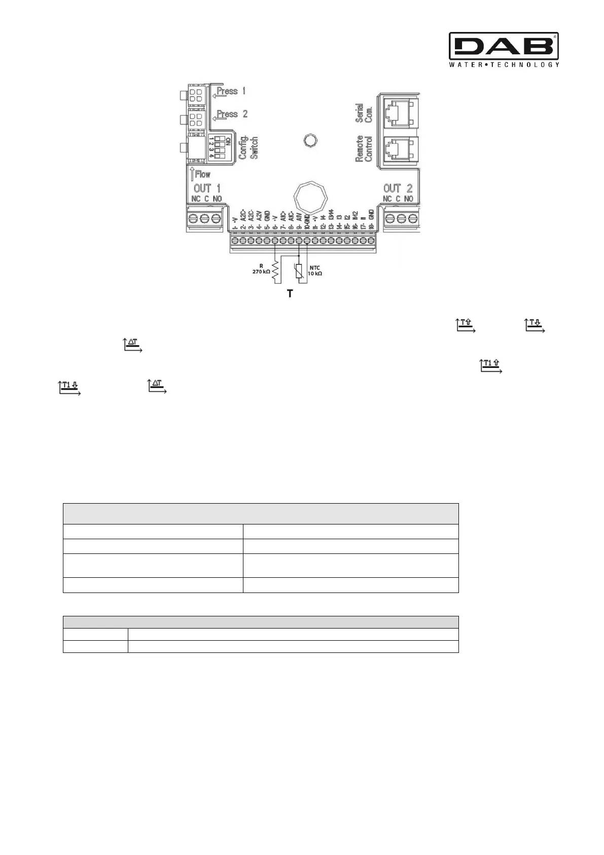
Figure 8: Connection of NTC sensor for temperature measurement T
N.B. Temperature reading via sensor T is only enabled in the following control modes: T constant increasing /decreasing
and ∆T constant .
N.B. Temperature reading via sensor T1 is only enabled in the following control modes: T1 constant increasing /decreasing
and ∆T constant .
For operating modes T constant and ∆T constant see paragraphs 7.1.5 and 7.1.6
N.B: The input of temperature sensor T type NTC is mutually exclusive with the 0-10V analogue input connected to the same poles of
the 18-pole terminal block.
5.5.4 Outputs
The connections of the outputs listed below refer to the two 3-pole terminal boards J3 and J4 indicated with the screen-printing OUT1
and OUT2 below which is also indicated the type of contact for the terminal (NC = Normally Closed, C = Common, NO = Normally
Open).
Characteristics of the output contacts
Max. bearable voltage [V]
Max. bearable current [A]
Max. accepted cable section [mm²]
Table 4: Characteristics of the output contacts
Functions associated with the outputs
Presence/Absence of alarms in the system
Pump running/Pump stopped
In the example shown in Figure 9 the light L1 is lit when there is an alarm in the system and it goes off when no kind of malfunction is
found, whereas the light L2 is lit when the pump is running and goes off when the pump is stopped (NC logic).