ENGLISH
41
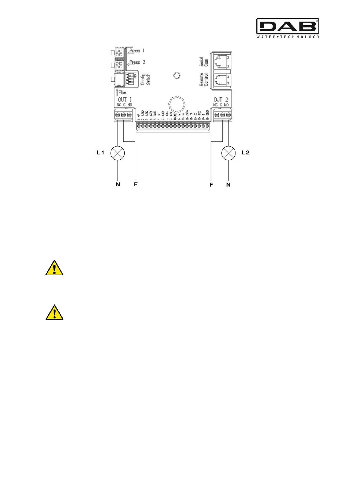
Figure 9: Example of Connection of Digital Outputs
5.6 Connection for Twin Systems
To make a twin system it is sufficient to connect the 2 inverters MCE-150/C using the cable supplied, fitting it onto both inverters in
one of the 2 connectors indicated by the word Link (see Figure 3).
For correct operation of the twin system, all the external connections of the input terminal board, except for input 3 which can be
managed independently, must be connected in parallel between the 2 MCE-150/C respecting the numbering of the individual terminals
(for example, terminal 17 of MCE-150/C -1 to terminal 17 of MCE-150/C -2 and so on).
If at the time of changing over between switching off one motor and switching on the other you hear a knocking
noise, proceed as follows:
1) hold down the central “menu” key for 5 seconds;
2) scroll through the parameters until you see ET;
3) increase the value of the ET parameter in the advanced menu until the noise disappears
For the possible operating modes of twin systems see par. 9.
6. START
All the starting operations must be performed with the MCE-150/C cover closed.
Start the system only when all the electrical and hydraulic connections have been completed.
Once the system has been started it is possible to modify the operating modes to adapt better to the plant requirements (see par. 9).
7. FUNCTIONS
7.1 Regulating Modes
MCE/C systems allow use of the following regulating modes:
− Regulation with constant differential pressure (factory setting).
− Regulation with constant curve.
− Regulation with constant curve with speed set by external analogue signal.
− Proportional differential pressure regulation depending on the flow present in the plant.
− T constant regulation
− ∆T constant regulation