ENGLISH
39
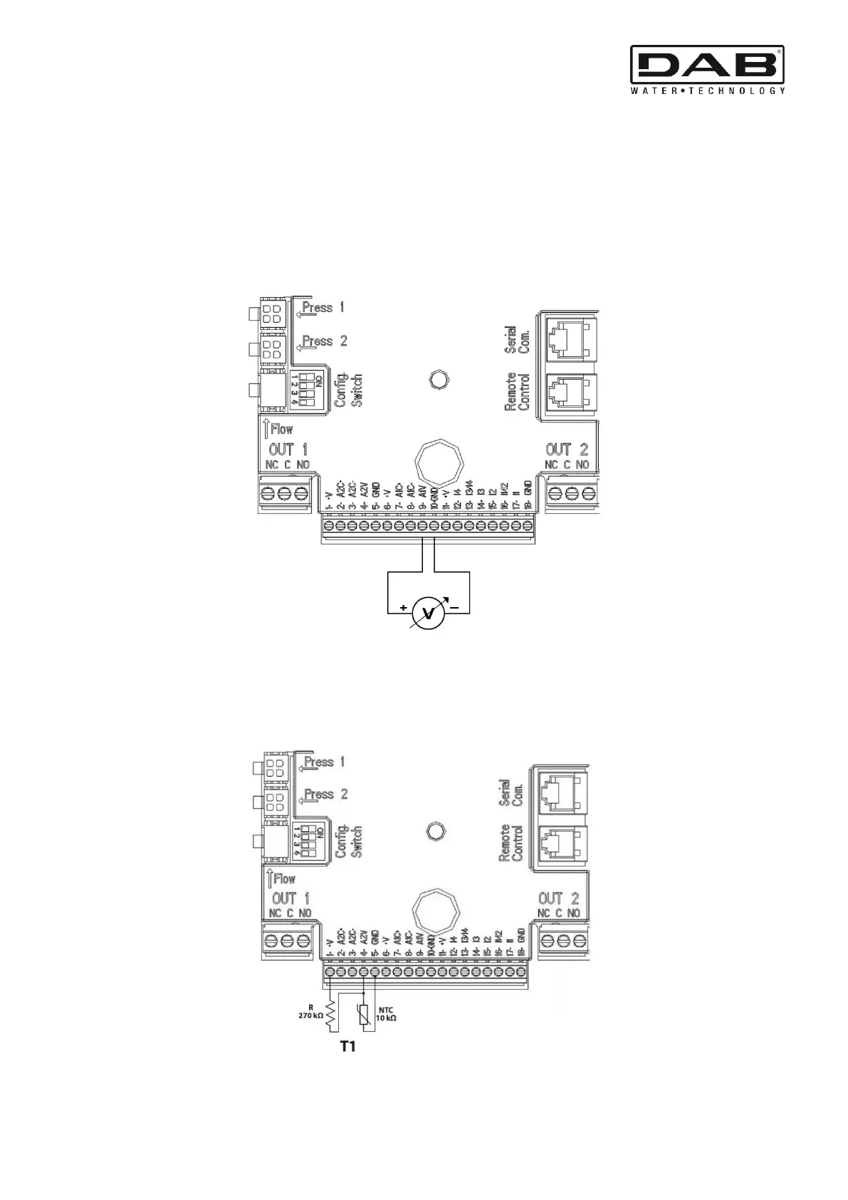
5.5.2 Analogue input 0-10V
The analogue input 0-10V is screen-printed at the base of the 18-pole terminal board:
- A1V (terminal 9): Positive pole
- GND (terminal 10): Negative pole
- A2V (terminal 4): Positive pole
- GND (terminal 5): Negative pole
The function associated with the analogue input A1V is that of regulating the pump rotation speed in proportion to the input
voltage 0-10V itself (see par. 7.1.3 and par. 9). The input A2V is not enabled.
See Figure 6 for an example of connection.
Figure 6: Example of Connection of Analogue Input
N.B: The 0-10V analogue input is mutually exclusive with the NTC type temperature sensor T connected to the same poles of the 18-
pole terminal block.
5.5.3 NTC wiring diagram for measuring the fluid temperature (T and T1)
For installation of the fluid temperature sensors T and T1, refer to the following wiring diagrams, see figure 7 and figure 8.
Figure 7: Connection of NTC sensor for temperature measurement T1