DIGITAL INDICATOR
DN500N
8
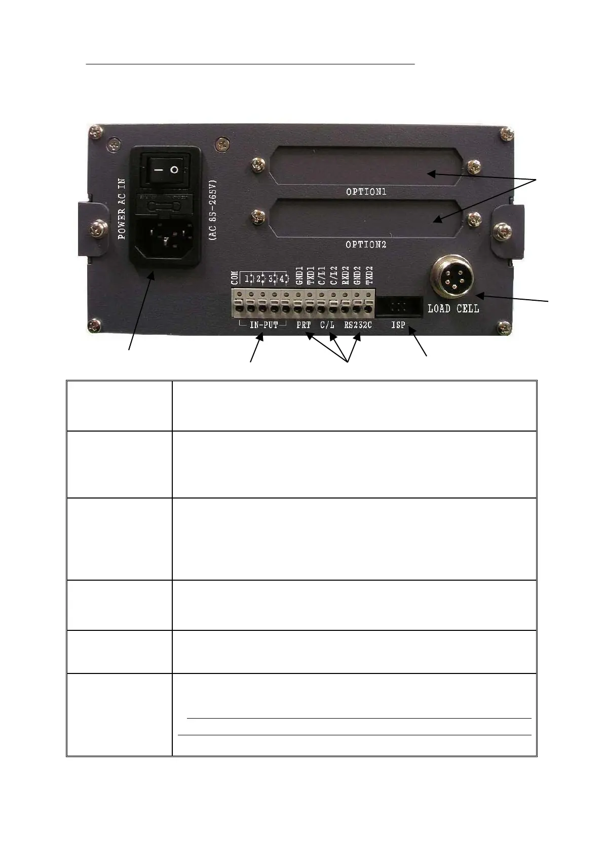
3-3. REAR PANEL
①POWER
-Power Switch : Power ON/OFF Switch
-Fuse : AC 250V 10A
-AC IN : This product can be used in AC 85V ~ 265V since it uses SMPS power.
②OPTION 1,2
- When OPTION BOARD is installed, I/F connector will be equipped.
- ANALOG out, Serial I/F, etc
③LOAD CELL
CONNECTOR (N-16)
-EXC + (+5V) PIN1 (RED)
-EXC - (-5V) PIN2 (WHITE)
-SIG+ PIN3 (BLUE or BLACK)
-SIG- PIN4 (GREEN)
-SHIELD PIN5 (OUTER COVER)
④
Remote-in-put
- It is used to control the equipment from the external operation panel.
(1.Start, 2.Stop, 3.Container, 4.Remove container)
* Refer to external input mode F-11
⑤External Output
(Printer, CURRENT,
Computer communication)
- RS-232C / CURRENT LOOP are built-in as standard
( GND,TXD1,CL1,CL2,RXD,GND,TXD )
⑥ISP
(DATA LOCK PIN)
- When LOCK pin header is built-in here, data can be protected from certain
external reasons of static electricity or system fault.
* When this Lock pin header is built in, data cannot be saved by pressing
keys on front for Function Setting since Lock function is being operated.
Please remove lock pin header before you do Setting again.
①
②
③
⑤④
⑥