EasyManua.ls Logo

dacell DN-100 User Manual

Default Icon
32 pages
To Next Page IconTo Next Page
Page #1 background imageLoading...
Page #1 background image
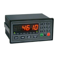
DIGITAL INDICATOR
USER’S MANUAL
DN-100 (VER 5.0)
DN-150 (VER 5.0)
DN-200 (VER 5.0)
DN-250 (VER 5.0)
DACELL CO.,LTD.
: 681-1 Cheoksan-ri, Nami-Myeon, Cheongwon-gun, Chung-
buk, Korea
TEL : 82-43-260-2242
FAX : 82-43-260-2245
http://www.dacell.com
E-Mail : dana@danaloadcell.com

Questions and Answers:

dacell DN-100 Specifications

General IconGeneral
Branddacell
ModelDN-100
CategoryMeasuring Instruments
LanguageEnglish

Summary

1. Special Features

1-1. Calibration Method

Two calibration systems: actual load and rated sensor output (mV/V).

1-2. Hold & Peak Hold Functionality

User can select between peak hold and sample hold modes for data retention.

1-3. Comparison Output Configuration

Configure limit values via front panel keys and output contact signal from the rear panel.

1-4. Data Back-up and Memory

Setup values stored on flash memory, retaining data after power interruptions.

1-5. Watch dog for System Stability

Automatic reset function to counter system halts caused by external factors like electrical noise.

2. Safety and Handling Precautions

2-1. Installation Environment and Safety

Ensure proper installation environment: avoid wetness, vibration, high temp/humidity, direct sun, dust, salt/ion. Ground properly.

2-2. Operational Safety Guidelines

During calibration, do not input unstable loads. Avoid pressing keys at discretion.

3. Technical Specifications

4. Front Panel Layout and Controls

4-1. DN-100/DN-200 Front Panel Details

Explains labels and functions of keys and LEDs on the front panel for DN-100 and DN-200 models.

4-2. DN-150/DN-250 Front Panel Details

Explains labels and functions of keys and LEDs on the front panel for DN-150 and DN-250 models.

5. Rear Panel Terminal Connections

5-1. Rear Panel Wiring and Safety Notes

Important notes on wiring, grounding, and device handling to prevent malfunction and ensure safety.

6. Wiring Diagram and Connections

7. Components and Functional Modes

7-1. Using Hold Mode Functionality

Explains different hold modes (Peak Hold, Sample Hold) and their activation via front panel or external input.

7-2. Comparison Output Function Usage

Details comparison output modes (Decision, High/Low Limit) and hysteresis settings.

8. Device Setting Modes

8-1. Overview of Setting Modes and Setup

Outlines four setting modes: Function, Digital Calibration, Actual Load Calibration, and SPAN Constant Calibration.

8-2. Function Mode Configuration

Details how to set various functions (F-01 to F-15) within the device's Function Mode.

8-3. Digital Calibration Procedure

Explains calibration using sensor output value and rated output/capacity from the calibration sheet.

8-4. Actual Load Calibration Method

Describes calibration by applying actual load (standard weight) to the sensor.

8-5. SPAN Constant Calibration

Details calibration using the S.CAL value, without requiring standard weight.

8-6. Data Back-up and Restore Operations

Instructions for saving and restoring device setup values to prevent data loss.

8-7. Key Lock Setup Procedure

Procedure to set up key lock to prevent accidental operation after calibration.

9. Product Inspection and Troubleshooting

10. Optional Interfaces

10-1. BCD Output Interface

Describes the BCD interface for outputting weight values in BCD coding, available for PLC and computers.

10-2. RS232C Communication Interface

Explains the RS232C interface, its wiring, communication parameters, and data stream format.

10-3. RS485 Communication Interface

Details the RS485 interface, including its type, method, baud rate, parity, data bit, stop bit, and command form.

Related product manuals