4. Front Pannel
4-1. DN-100, DN-200
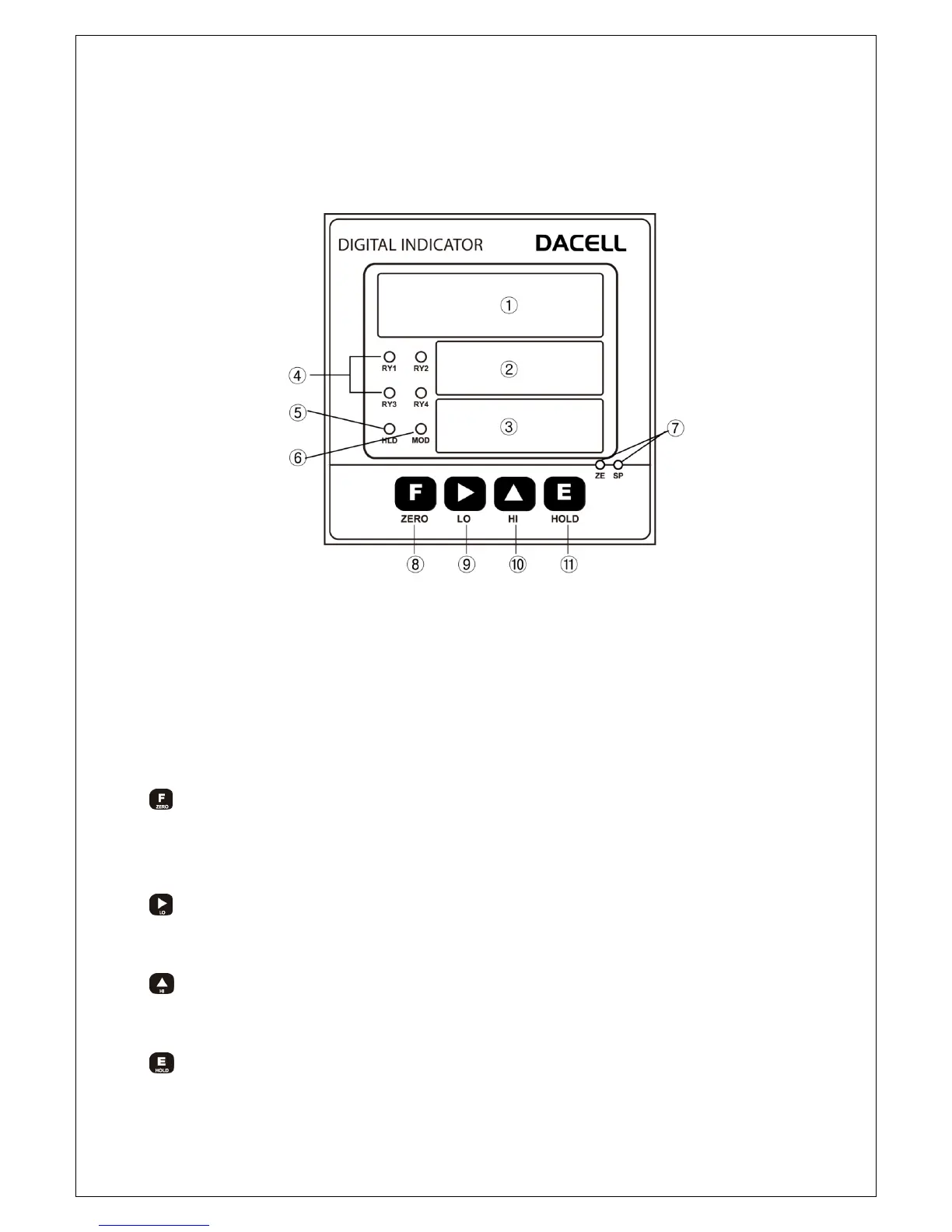
① Measure value : Indicate measured value or setting value..
②,③
Setting value HI, LO
: Indicate setting value HI, LO
④ Relay LED : Light a LED when measured data are beyond setting value or less.
⑤ HOLD LED : This LED will be lighted when the measured value is on Hold
⑥ Modulation LED : Indicated only when measured data is unstable.
⑦ ZERO/SPAN setting up VR
: It is used when ZERO and SPAN calibration of Analog output (DC 0 ~ 10V or 4 ~
20mA) is carried out.
⑧
:Measruing Mode: Once this Key is pressed for more than 1 second, the current
measuring value will be Zero (0) and the Analog output will be 0V (4mA) as well.
SET-UP Mode: Once this is pressed on the Function Set-up Mode, you will return to
the measuring mode.
⑨
Measuring Mode: Once this Key is pressed, the lower limit setting value will be
displayed and this value also can be changed.
SET-UP Mode: The location of row for the number flickering can be moved.
⑩
Measuring Mode: Once this Key is pressed, the upper limit setting value will be
displayed and the value can be changed.
SET-UP Mode: The flickering number will be increased by 1 and 1.
⑪ Measuring Mode: Once this Key is pressed, HOLD will be selected and once this
key is pressed again, HOLD will be cancelled.
5
SET-UP Mode: Save each set-up value.