Do you have a question about the dacell DN-30W and is the answer not in the manual?
Lists key features like calibration methods, hold modes, comparison output, data backup, and watch dog.
Guidelines for safe installation, including environmental considerations and wiring practices.
Precautions for correct operation, especially during calibration and general usage.
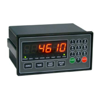
Description of buttons, display, and LEDs on the front panel for operation and status.
Details and descriptions of all terminals on the rear panel for wiring and input/output.
Visual guides for connecting sensors, power, and communication for various DN models.
Explains how to use Peak Hold and Sample Hold modes for capturing measured values.
Details the four comparison modes (Decision, High, Low, Low&High) and their relay outputs.
Introduces Function, Digital Calibration, and Actual Load Calibration modes.
Covers how to set function modes, relay data, and lists all available function parameters.
Step-by-step guide for calibrating the indicator using sensor output values.
Method for calibrating with applied loads and compensation.
Procedures for saving and loading device configuration settings.
Procedure to prevent accidental operation by locking front panel keys.
Details of the programmable BCD interface for outputting weight values to PLC or computers.
Information on RS232C and RS485 serial communication wiring, ports, and settings.
Explanation of standard ASCII and Modbus RTU protocols for data communication.
| Type | Digital Multimeter |
|---|---|
| Diode Test | Yes |
| Continuity Buzzer | Yes |
| Data Hold | Yes |
| Power Supply | 9V Battery |
| DC Voltage Range | 200mV/2V/20V/200V |
| AC Voltage Range | 200V |
| DC Current Range | 200μA/2mA/20mA/200mA/10A |
| Resistance Range | 200Ω/2kΩ/20kΩ/200kΩ/2MΩ |
| Display | 3 1/2 Digit LCD |
| Operating Temperature | 0°C - 40°C |