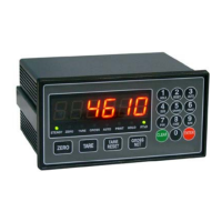
⑴ DN-10W, DN-20W, DN-25W, DN-27W, DN-30W, DN-50W
Please check the location of terminal and its use. While the projected button is being
pressed, please insert the cable into the lower hole completely. As soon as you release
the button, the connection will be completed. At the point, please slightly pull the calbe
and check whether the cable is come off or not.
(The most suitable calbe is Φ 0.5~1. Linking cable must be brazing or used with 1
terminal)
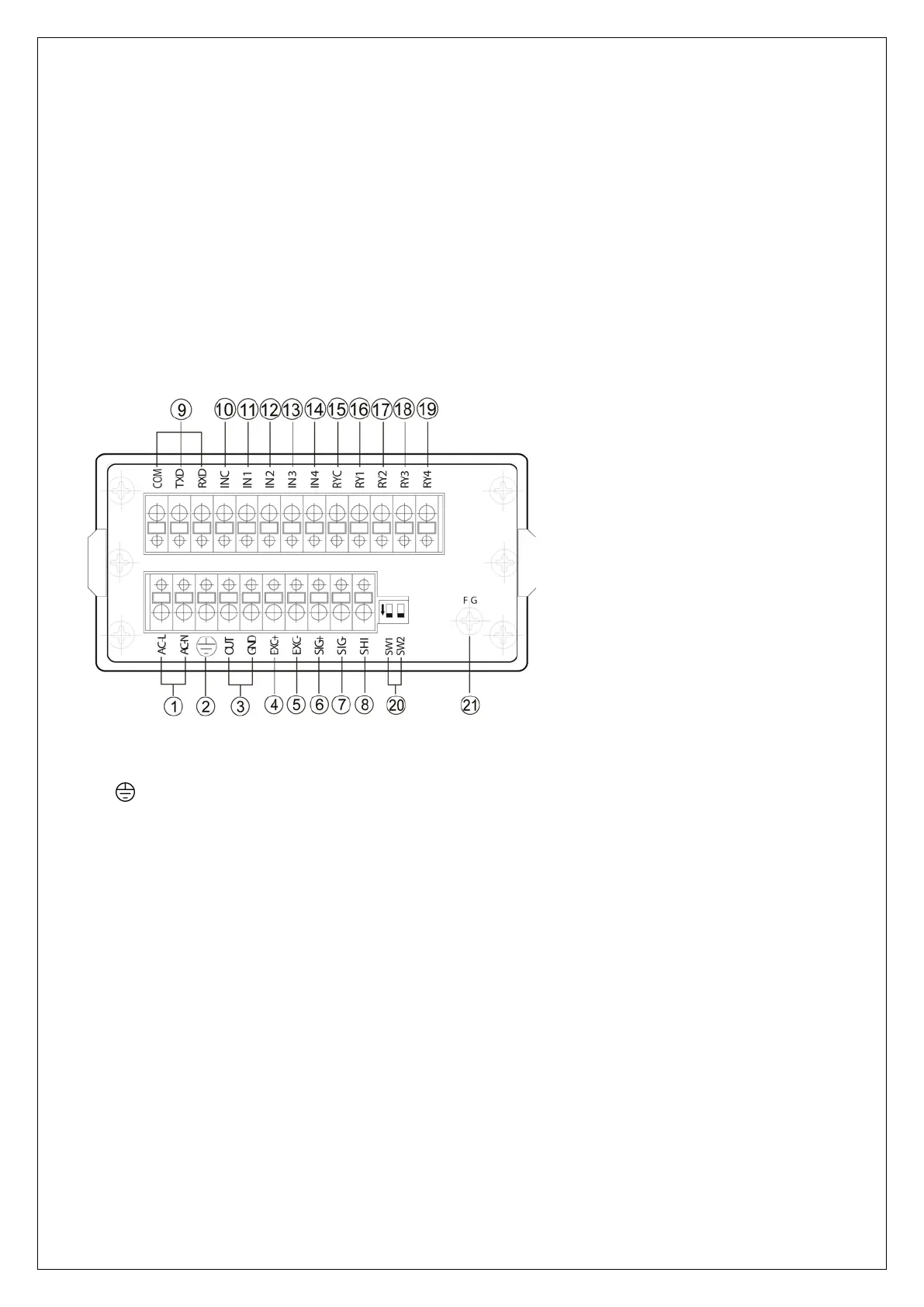
① AC IN : Main Power Supply Wiring Terminal
② : Ground Terminal (as an independent ground connection.)
③ OUT : Analog (DC 0 ~10V/DC 4 ~ 20mA) Output Terminal
④ EXC+ : Sensor Supply Voltage + Connection Terminal
⑤ EXC- : Sensor Supply Voltage + Connection Terminal
⑥ SIG+ : Sensor Ouput Signal + Connection Terminal
⑦ SIG- : Sensor Output Signal – Connection Terminal
⑧ SHI : SHIELD connection terminal of sensor
⑨ GND, TXD, RXD : RS232C SERIAL INTERFACE (RS485 : TXD → TX+, RXD → TX-)
⑩ INC : External Input Common Terminal
⑪ IN1 : External HOLD Input Terminal
⑫ IN2 : External ZERO Input Terminal
⑬ IN3 : External printer signal Input Terminal (when PT-100 use)
⑭ IN4 : No use
⑮ RYC : RELAY Output Common Terminal
⑯ RY1 : RELAY 1(Lower Limit) Output Terminal