○
17E
A RY2 : RELAY2 (Upper Limit) Output Terminal
A○
18E
A RY3 : RELAY3( Normal) Output Terminal (OK )
A○
19E
A RY4 : RELAY 4 Output Terminal
A○
20E
A SW1, 2 :
• DN-10W, DN-25W, DN-27W, DN-30W, DN-50W : NC
• DN-20W :
Sensor supply voltage setting Sensor output signal setting
DC10V DC24V 0 ~ 10V 4 ~ 20mA
SW1 OFF ON -
SW2 - OFF ON
※ When use Potentiometer (Model LPS,LPM) : SW1 and SW2 OFF
A○
21E
A FG : Frame ground terminal
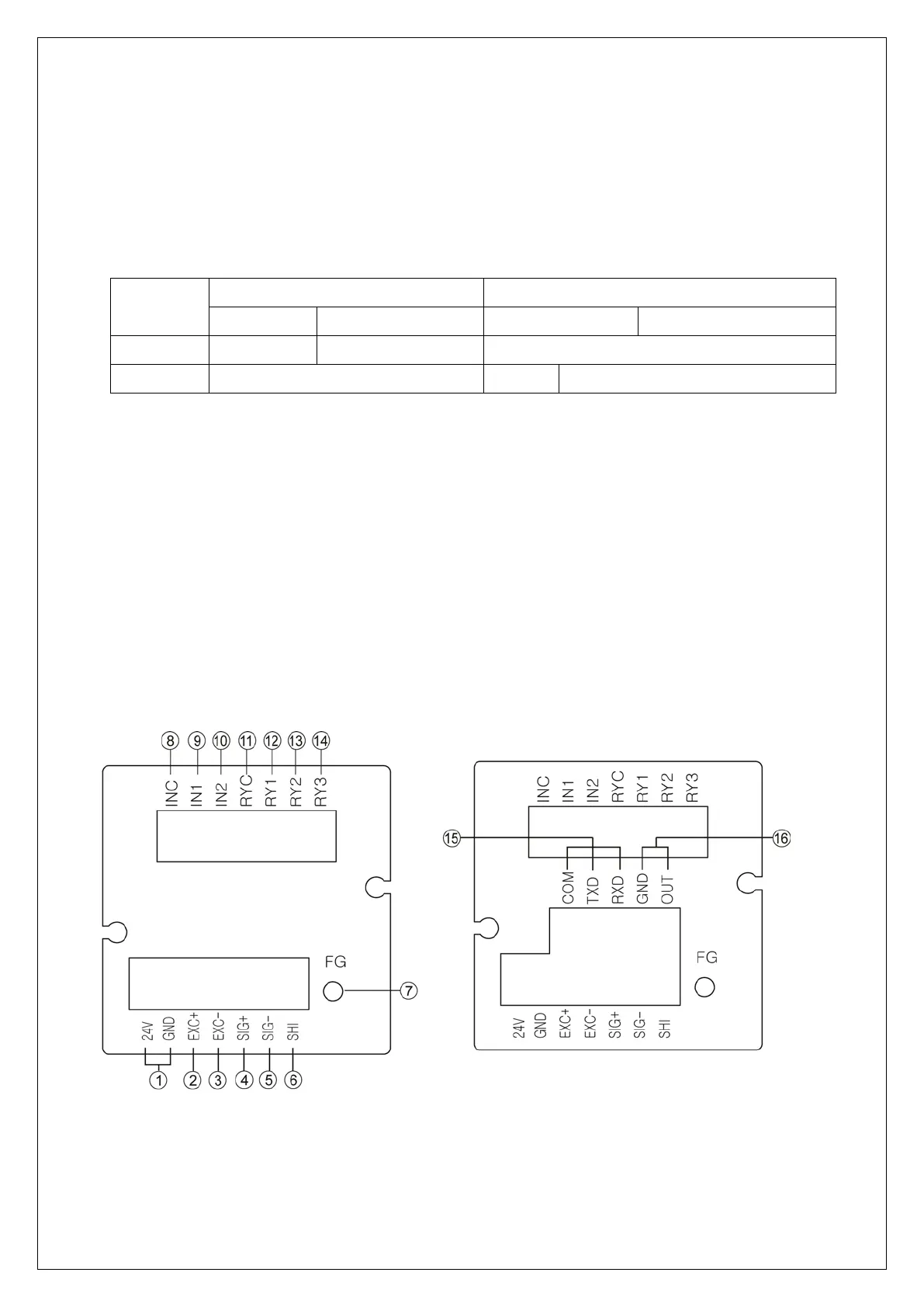
⑵ DN-70, DN-80
Please check the location of terminal and its use. While the projected button is being
pressed, please insert the cable into the lower hole completely. As soon as you release
the button, the connection will be completed. At the point, please slightly pull the calbe
and check whether the cable is come off or not.
(The most suitable calbe is Φ 0.5~1. Linking cable must be brazing or used with 1
terminal)
① 24V : DC24V (Main Power)
② EXC+ : Sensor Supply Voltage + Connection Terminal
③ EXC- : Sensor Supply Voltage + Connection Terminal