Electrical Specifications
WARNING
The electriC service for the raised vent should be installed
only by a licensed electrician.
It is the owner's responsibility to ensure that the electrical
connection of this appliance is performed by a qualified
electrician. The electrical installation, including minimum
supply wire size and grounding, must be in accordance
with the National Electric code ANSI/NFPA 70- 2002* (or
latest revision) and local codes and ordinances.
*A copy of this standard may be obtained from:
National Fire Protection Association
1 Batterymarch Park
Quincy, Massachusetts 02269-9101
Electrical Supply Requirements
Power must be supplied by a separate, grounded, single
phase circuit protected by a properly sized circuit breaker
or time delay fuse and rated at 120 Vac, 60 Hz, 15Amps.
• The above specifications are for reference only. If the
power supply requirements shown above do not agree
with those listed on the product data label, use the rat-
ings on the label.
• The suggested location of the junction box supplying
power to the unit is to the bottom right of the unit, pro-
viding local codes permit.
• Install 3 conductor wiring/conduit with minimum cur-
rent carrying capacity of 8 Amps to supply power to the
blower from the raised vent when turned on. See the
following pages for further details.
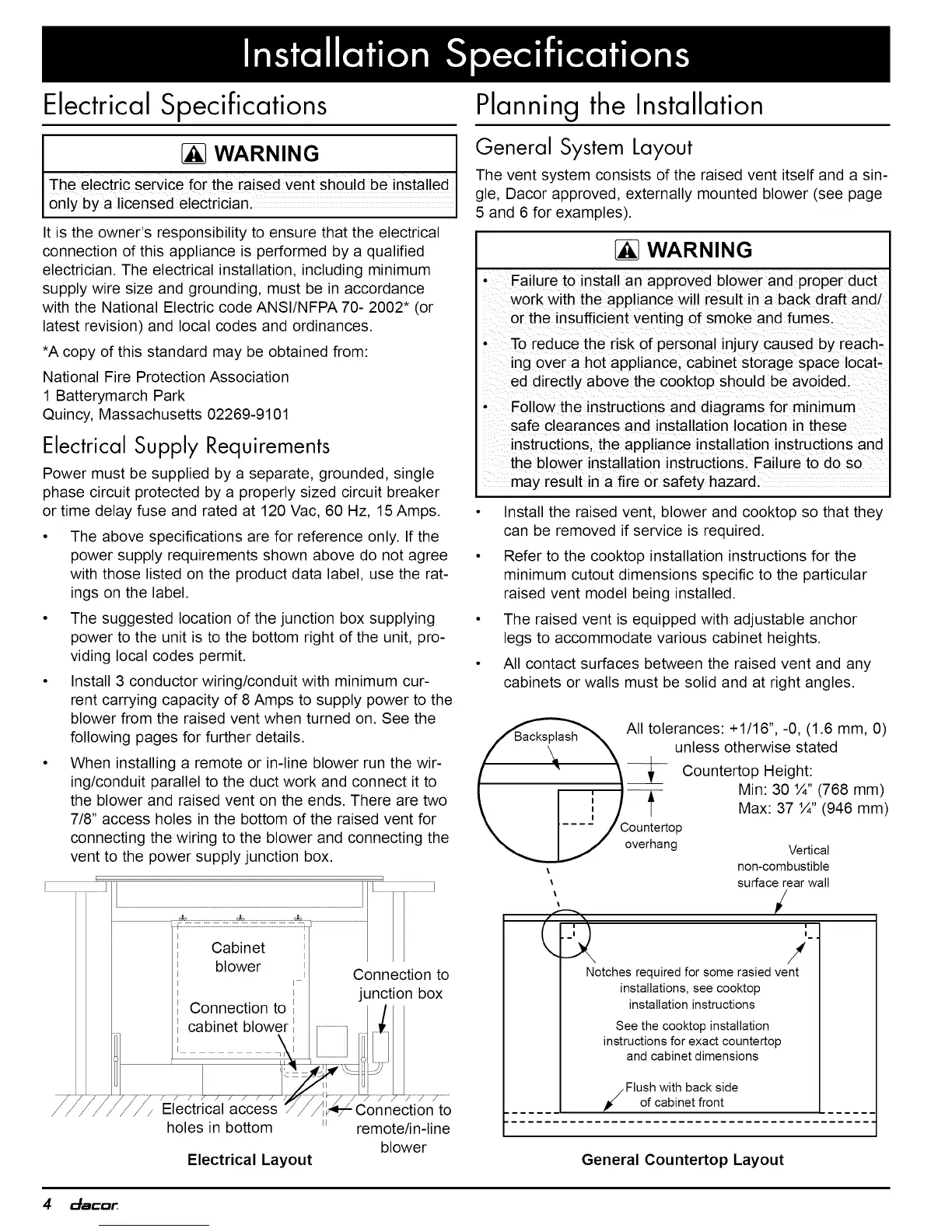
When installing a remote or in-line blower run the wir-
ing/conduit parallel to the duct work and connect it to
the blower and raised vent on the ends. There are two
7/8" access holes in the bottom of the raised vent for
connecting the wiring to the blower and connecting the
vent to the power supply junction box.
!..........................
holes in bottom
Electrical Layout
remote/in-line
blower
Planning the
Installation
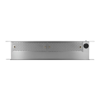
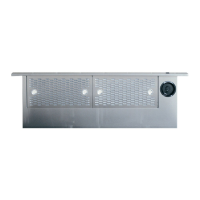
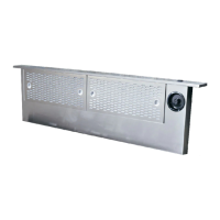
General System Layout
The vent system consists of the raised vent itself and a sin-
gle, Dacor approved, externally mounted blower (see page
5 and 6 for examples).
WARNING
• Failure to install an approved blower and proper duct
work with the appliance will result in a back draft and/
or the insufficient venting of smoke and fumes.
• To reduce the risk of personal injury caused by reach-
ing over a hot appliance, cabinet storage space locat-
ed directly above the cooktop should be avoided.
Follow the instructions and diagrams for minimum
safe clearances and installation location in these
instructions, the appliance installation instructions and
the blower installation instructions. Failure to do so
may result in a fire or safety hazard.
• Install the raised vent, blower and cooktop so that they
can be removed if service is required.
• Refer to the cooktop installation instructions for the
minimum cutout dimensions specific to the particular
raised vent model being installed.
The raised vent is equipped with adjustable anchor
legs to accommodate various cabinet heights.
All contact surfaces between the raised vent and any
cabinets or walls must be solid and at right angles.
AII tolerances: +1/16",-0, (1.6 mm, 0)
unless otherwise stated
_ Countertop Height:
Min: 30 %",,(768 mm)
\ I i / | Max: 37 '/4 (946 mm)
\ I.... / Countertop
_,_...._.,i / °verhang
%
L:2
Vertical
non-combustible
surface rear wall
i
i
i
/
Notches required for some rasied vent
installations, see cooktop
installation instructions
See the cooktop installation
instructions for exact countertop
and cabinet dimensions
Flush with back side
of cabinet front
General Countertop Layout
4 _mC_