(4) Pin Description
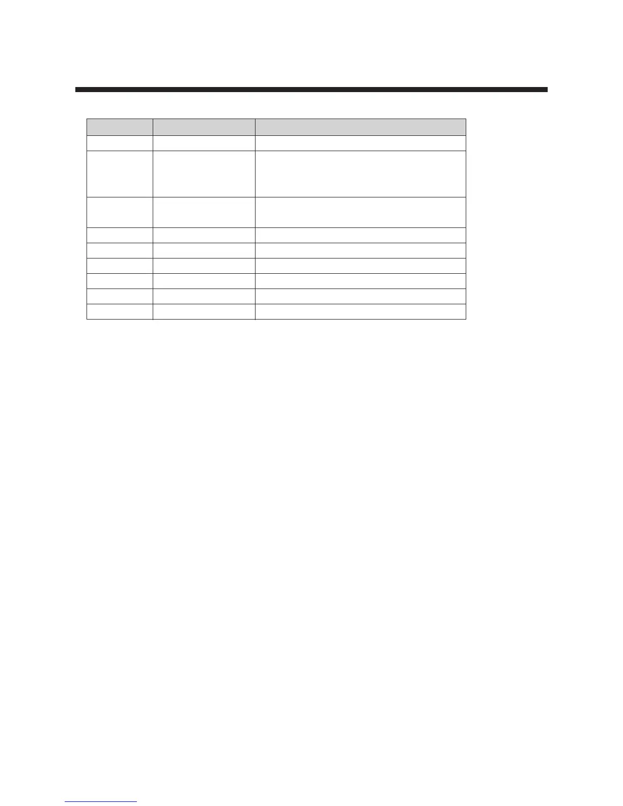
PIN SYMBOL DESCRIPTION
1,2,3,4 K0,K1,K2,K3 4 bit input port with built in pull up resistor
5,6,7,8,9,10 D0,D1,D2,D3,D4,D5 10 bit output port which can be set or reset pin
by pin independently.
The output structure is N-channel open drain.
11 REMOUT remote control signal output port which has
high current driving capability
12 OSC 2 oscillator output
13 OSC 1 oscillator input
14 Vdd 2-4V power supply
15 RESET reset signal input which is a low active
16 GND ground
17,18,19,20 R0,R1,R2,R3 4 bit programmable I/O port
31