ALIGNMENT INSTRUCTIONS
2. ASSEMBLY ADJUSTMENTS
1) SCREEN ADJUSTMENT(S2)
Enter the service mode and select service adjustment S2
You can see the horizontal straight line on the screen
Adjust the Screen Control volume(located on FBT) so that the horizontal straight line on screen may be disappear.
Press the MENU button to exit the screen adjustment mode.
2) FOCUS ADJUSTMENT(S2)
Turn in a local station and the Focus Control volume(located on FBT) for best picture details at light condition.
3) RF-AGC ADJUSTMENT(S5)
Receive a good local channel.
Enter the service mode and select service adjustment S5
You can see the OSD as shown in below.
Select AGC item, press volume up (
U
) or down( ) buttons until noise or beet in picture disappears.
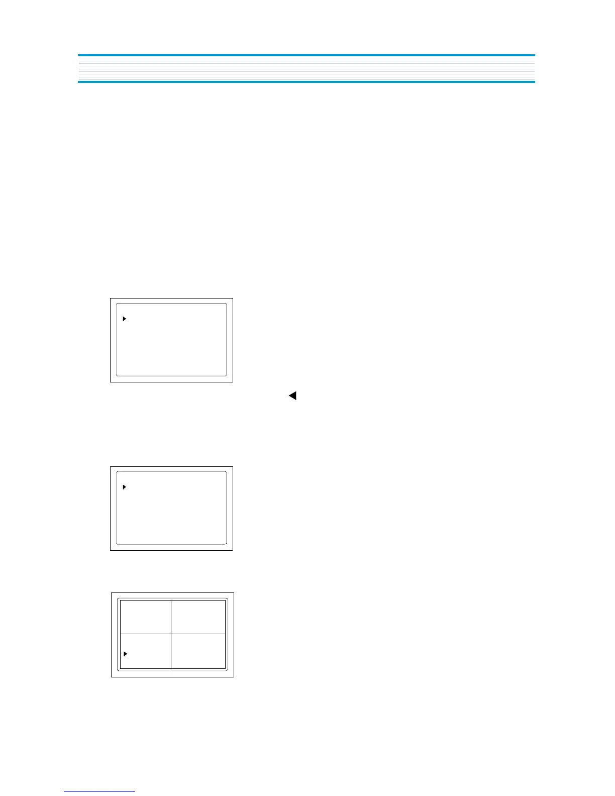
4) GEOMETRIC ADJUSTMENT(S6)
Enter the service mode and select service adjustment S6
You can see the OSD as shown in below.
Use the CH up ( ) or down ( ) buttons to select "CROSS BW" item.
Use the VOL up (
U
) button to select internal cross pattern.
AGC Auto
IF CONTROL
AGC Vol 3.75V
AGC 000
VIDEO LEV
005 FM LEV
007
HFREQ 032
CROSS BW
H CENTER
GEOMETRY
V SIZE 060
V CENTER 040
V SC
020 V LIN
000
NO SD POWER OFF NO
CROSS BW
020
HBLKR 1 HBLKL 6
H CENTER
GEOMETRY
V SIZE 060
V CENTER 040
V SC
020
V LIN
000
NO SD POWER OFF NO
CROSS BW
020
HBLKR 1 HBLKL 6
- Figure1 -
 Loading...