- 62 -
Service manual WP 895/895F, CP885/885F, CP485F
5-10 TV start-up, TV normal run and stand by mode operations
5-10-1 TV start-up operations
*
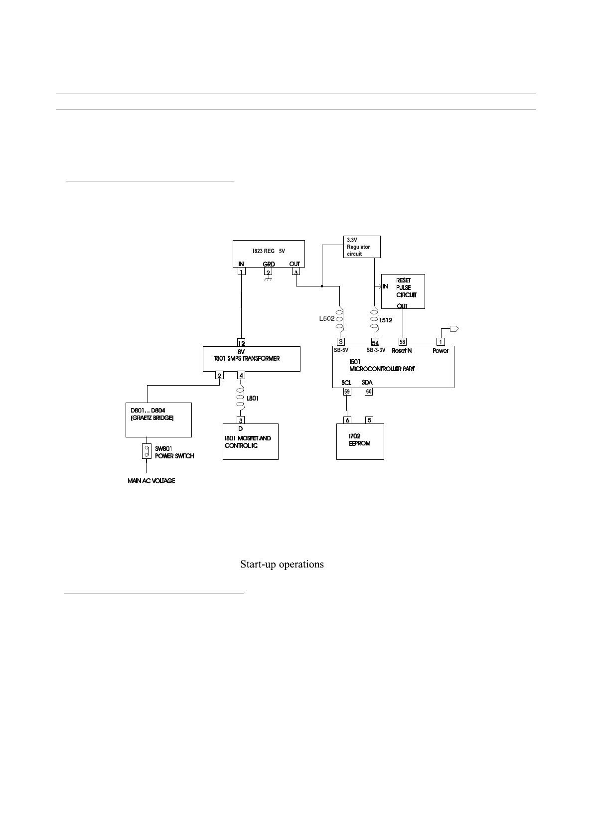
Schematic diagram for start-up operations
*
TV start-up and microcontroller initialisation
- When SW801 power switch is pushed, main AC voltage is applied to T801 transformer (after rectification by D801...
D804 diodes). Then, T801 SMPS transformer starts operating and supplies DC voltage to I823 (5V regulator) and
- There re gulators pro vide 5V / 3.3V DC v oltag e to I501 micr ocontroller po wer suppl y pins (pin 3 / pin 54) and to the
reset pulse circuit whic h provides r eset pulse to I501 microcontroller reset pin (pin 58).
- Then, the microcontroller starts its initialisation. Its po wer pin (pin 1) is set to high which allo ws deli very of po wer
supply v olta ges (123V~143V , 8V, 5V...). At this ste p, all IC ’s start w orking b ut no picture appears on screen: I501 IC
doesn ’t pro vide hor izontal dri ve voltage.
- Then, the microcontroller consults I702 EEPR OM via I2C b us to kno w the last TV set mode (normal run mode or
stand-by mode ) bef ore switching of f.
to 3.3v Regulator circuit.