©
200518 3-27
Inspection and adjustment
EXPLANATORY NOTES ON THE MAINTENANCE ACTIVITIES
ΧΦ65/65 (II) series
5
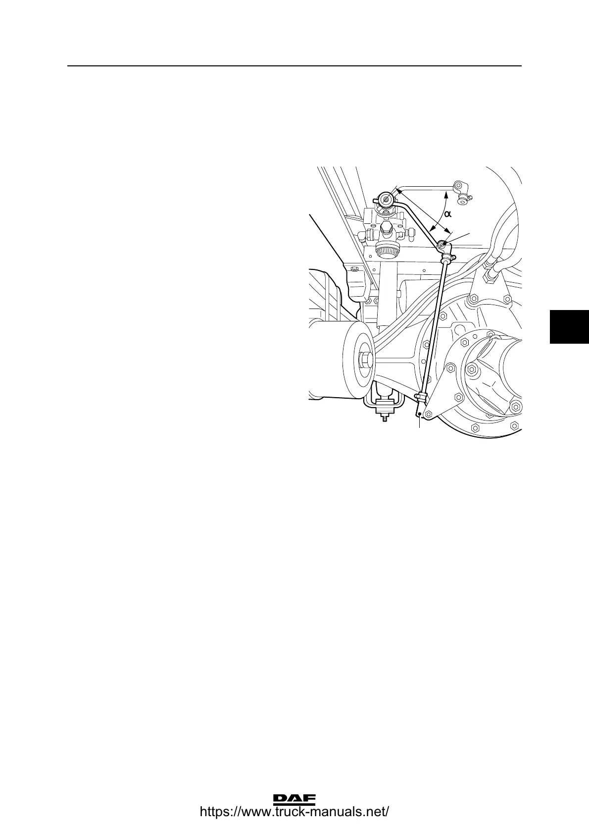
9. Read the brake pressure of the rear axle
from pressure gauge 2 and check that this
value matches the one listed on the
instruction plate in the table under "output
pressure p2" to the rear axle.
10. Correct, if necessary, the brake pressure by
moving the rubber sleeve (1) in relation to the
vertical connecting rod. On no account
change the length L of the (horizontal)
control lever.
11. Remove the rubber sleeve (2) and move the
control lever towards maximum load. Check
that the output pressure is now allowed
through (almost) without reduction.
Note:
The small socket head screw in the centre of the
valve must not be adjusted.
Drive and chas sis
L
R600781
1
2
https://www.truck-manuals.net/