2
VTO Connections
Home System Configuration
VTNS1060A
VTH1550CH
When conguring a home VDP system, all devices should rst be connected together. Usually, this is done by connecting both the
camera unit (VTO) and monitor unit (VTH) to the VTNS1060A PoE switch.
The VTNS1060A is a 24v passive PoE unit, this is a different type of PoE than that seen on conventional IP devices. As such, both the
VTO2000A and VTH1550CH can only be used with 24v passive PoE or by connecting a 12/24vdc power supply to the power input
terminals on the units.
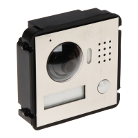
VTO2000A
24v PoE 24v PoE
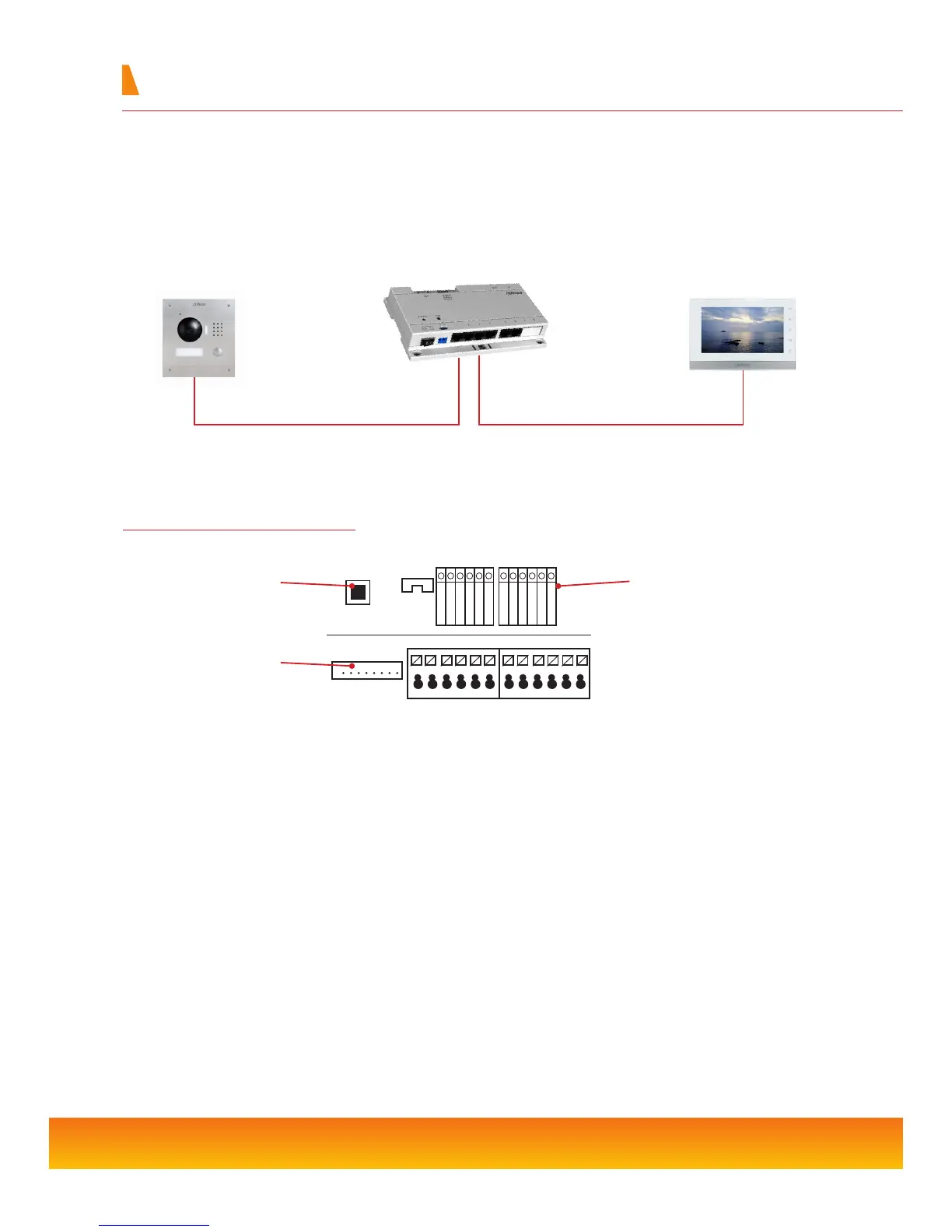
Tamper Switch Sounds an alarm in the event that the VTO unit is tampered with
Network Connection Connect the supplied RJ45 adapter cable to this port
+12/24v Used when not powering the VTO via PoE, connect the 12v or 24v DC positive supply to this
terminal
GND Ground connection for 12v or 24v DC negative supply and other inputs
12v Out DC 12v continuous output for auxillary device
Unlock Button Input to connect a switch such as a push button for releasing the door lock
Feedback Input for door contact to check if the door is closed before engaging lock
NO/NC/COM Relay output used when unlocking door
Tamper
Switch
NET
Network
Connection
Inputs &
Outputs
+12V/+24V
+12V_OUT
FEEBBACK
UNLOCK BUTTON
GND
GND
NO
NC
COM
GND
485_A
485_B
 Loading...