48 WGZ030D through WGZ200D OMM 1130
10 seconds later if the pressure is still above the unload set point. On that circuit’s VIEW CIRCUITn (1)
screen is displayed the “Hold Clear @” value which is the limit by which the condenser pressure must
drop to allow for additional loading. A High Condenser Pressure Unload event will be recorded in the
Event Log.
No stage up will be allowed on the circuit until the condenser pressure drops below the unload set point
less an offset value which is calculated based on 1) type refrigerant, 2) number of compressors, 3)
condenser configuration, and 4) how many high pressure unload occurrences since the previous mid-
night. See below for initial offset value and step-increase for each additional occurrence.
Hold Clear Reset Value =
High Pressure Unload set point – [“Initial Offset” + [“Step-Increase” x [“number of occurrence”-1]]]
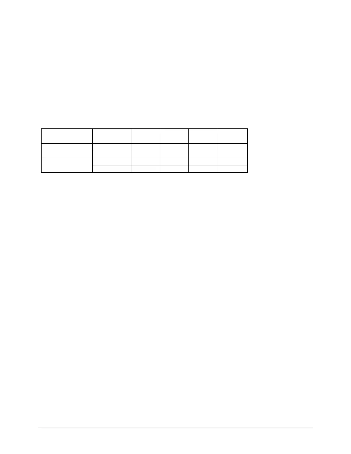
Initial Offset & Step Increase
Condenser
Configuration
No. of
Compressors
R410A
R22,
R407C
R134a
Step
Increase
4 40 psi 30 psi 30 psi 10 psi
Water-Cooled
6 32 psi N/A 20 psi 10 psi
4 100 psi 70 psi N/A 15 psi
Air-Cooled
6 80 psi N/A N/A 15 psi
Example of Operation: Assume a packaged water-cooled WGZ unit with 4 compressors using R410A as the
refrigerant. Circuit number one is fully loaded (both compressors running) when that circuit’s condenser
pressure exceeds the High Condenser Pressure Unload set point. Circuit number one will unload by turning
one of the two compressors off immediately. This circuit will not be allowed to load back up until its
condenser pressure decreases below the “Hold Clear @” value which is displayed on the “VIEW CIRCUIT 1
(1)” screen. Since this is the first High Condenser Pressure – Unload occurrence for that circuit, the circuit
will be allowed to load once the condenser pressure drops below the High Condenser Pressure Unload set
point minus 40 psi. If using default value (405 psi) this will be 365 psi. After some time, the condenser
pressure is allowed to decrease below this value and circuit number one is again allowed to load up. Again its
condenser pressure exceeds the High Condenser Pressure Unload set point and it unloads. Because this is the
second High Condenser Pressure – Unload occurrence for that circuit, the circuit will not be allowed to load
until the condenser pressure drops below the High Condenser Pressure Unload set point minus 50 psig (40
psi plus step-increase10psi). If using default values, this will be 355 psi. As you can see, for each occurrence
the discharge pressure must get lower and lower (based on Step-Increase value) before the circuit is allowed
to again load. This logic is intended to prevent excessive cycling of compressors.
Unit Capacity Overrides
The following conditions shall override the automatic capacity control when the chiller is in cool mode
only.
Demand Limit
The maximum unit capacity can be limited by a 4 to 20 mA signal on the Demand Limit analog input.
This function is only enabled if the Demand Limit set point is set to ON. The maximum unit capacity
stage is determined as shown in the following graph.


 To Next Page