EasyManuals Logo

Daikin 2AMX40G3V1B User Manual

Daikin 2AMX40G3V1B
267 pages
To Next Page IconTo Next Page
To Previous Page IconTo Previous Page
Page #43 background imageLoading...
Page #43 background image
SiBE121123_A Indoor Unit
Printed Circuit Board Connector Wiring Diagram 32
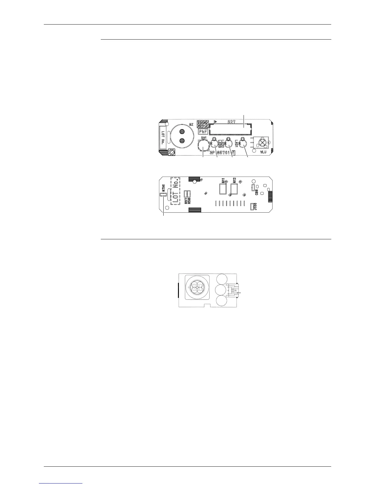
Display PCB
INTELLIGENT
EYE Sensor PCB
1) S27 Connector for control PCB
2) SW1 (S1W) Forced cooling operation [ON/OFF] button
3) LED1 (H1P) LED for operation (green)
4) LED2 (H2P) LED for timer (yellow)
5) LED3 (H3P) LED for INTELLIGENT EYE (green)
6) RTH1 (R1T) Room temperature thermistor
S27
SW1
(Solder side)
LED2LED3 LED1
RTH1
3P185701-3
1) S36 Connector for control PCB
S36
3P296737-1

Table of Contents

Other manuals for Daikin 2AMX40G3V1B

Questions and Answers:

Question and Answer IconNeed help?

Do you have a question about the Daikin 2AMX40G3V1B and is the answer not in the manual?

Daikin 2AMX40G3V1B Specifications

General IconGeneral
BrandDaikin
Model2AMX40G3V1B
CategoryAir Conditioner
LanguageEnglish

Related product manuals