17 | Technical data
Installer reference guide
72
2(A)MXM40+50 + 2(A)MXF40+50
R32 Split series
4P600463-2C – 2020.08
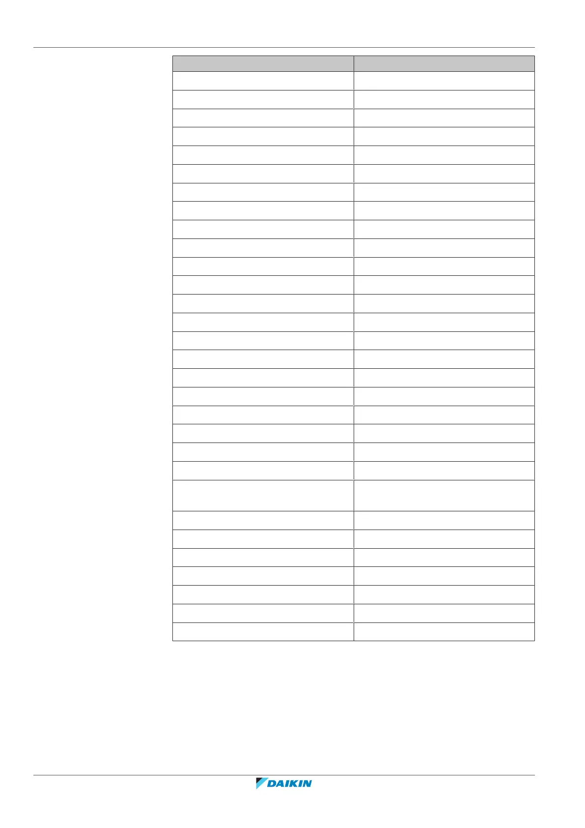
Symbol Meaning
Q*M Thermo switch
Q*R Residual current device
R* Resistor
R*T Thermistor
RC Receiver
S*C Limit switch
S*L Float switch
S*NG Refrigerant leak detector
S*NPH Pressure sensor (high)
S*NPL Pressure sensor (low)
S*PH, HPS* Pressure switch (high)
S*PL Pressure switch (low)
S*T Thermostat
S*RH Humidity sensor
S*W, SW* Operation switch
SA*, F1S Surge arrester
SR*, WLU Signal receiver
SS* Selector switch
SHEET METAL Terminal strip fixed plate
T*R Transformer
TC, TRC Transmitter
V*, R*V Varistor
V*R Diode bridge, Insulated-gate bipolar
transistor (IGBT) power module
WRC Wireless remote controller
X* Terminal
X*M Terminal strip (block)
Y*E Electronic expansion valve coil
Y*R, Y*S Reversing solenoid valve coil
Z*C Ferrite core
ZF, Z*F Noise filter
17.2 Piping diagram: Outdoor unit
Component PED category classification:
▪ High pressure switches: category IV
▪ Compressor: category II
▪ Other components: refer to PED article 4, paragraph 3