6 Electrical installation
Installation manual
14
ETVH/X16S18+23EA6V+9W
Daikin Altherma 3 H HT F
4P644728-1 – 2021.02
Backup
heater type
Backup
heater
capacity
Power
supply
Maximum
running
current
Z
max
*9W 3kW 3N~400V 4A —
6kW 3N~400V 9A —
9kW 3N~400V 13A —
(a)
6V
(b)
Electrical equipment complying with EN/IEC 61000-3-12
(European/International Technical Standard setting the limits for
harmonic currents produced by equipment connected to public
low-voltage systems with input current >16A and ≤75A per
phase).
(c)
This equipment complies with EN/IEC61000‑3‑11 (European/
International Technical Standard setting the limits for voltage
changes, voltage fluctuations and flicker in public low-voltage
supply systems for equipment with rated current ≤75A) provided
that the system impedance Z
sys
is less than or equal to Z
max
at the
interface point between the user's supply and the public system. It
is the responsibility of the installer or user of the equipment to
ensure, by consultation with the distribution network operator if
necessary, that the equipment is connected only to a supply with
a system impedance Z
sys
less than or equal to Z
max
.
(d)
6T1
Connect the backup heater power supply as follows:
a Factory-mounted cable connected to the contactor of the
backup heater, inside the switch box (K5M)
b Field wiring (see table below)
Model (power
supply)
Connections to backup heater power
supply
*6V (6V: 1N~230V)
1N~, 50 Hz
230 V AC
SWB
4
3
6
5
2
1
K5M
14
13
Q1DI
1
2
3
4
5
6
7
8
F1B
II I I
NL
X6M
BRN
GRY
BLU1
BLU2
Model (power
supply)
Connections to backup heater power
supply
*6V (6T1: 3~230V)
SWB
3~, 50 Hz
230 V AC
4
3
6
5
2
1
K5M
14
13
1
2
3
4
5
6
7
8
F1B
II I I
Q1DI
L1 L2 L3
X6M
BRN
GRY
BLU1
BLU2
*9W (3N~400V)
3N~, 50 Hz
400 V AC
SWB
Q1DI
L1 L2 L3 N
1
2
3
4
5
6
7
8
F1B
II I I
X6M
2
1
K5M
4
3
6
5
14
13
BRN
GRY
BLK
BLU
F1B Overcurrent fuse (field supply). Recommended fuse:
4‑pole; 20A; curve 400V; tripping class C.
K5M Safety contactor (in the lower switch box)
Q1DI Earth leakage circuit breaker (field supply)
SWB Switch box
X6M Terminal (field supply)
NOTICE
Do NOT cut or remove the backup heater power supply
cable.
6.3.3 To connect the shut-off valve
INFORMATION
Shut-off valve usage example. In case of one LWT zone,
and a combination of underfloor heating and heat pump
convectors, install a shut-off valve before the underfloor
heating to prevent condensation on the floor during cooling
operation. For more information, see the installer reference
guide.
Wires: 2×0.75mm²
Maximum running current: 100mA
230VAC supplied by PCB
[2.D] Shut off valve
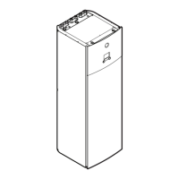
1 Open the following (see "4.2.1To open the indoor unit"[45]):
 Loading...
