4 Unit installation
Installation manual
5
EHFH03S18D
Daikin Altherma 3 R F
4P596803-1D – 2022.08
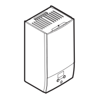
4.1.1 Installation site requirements of the
indoor unit
▪ The indoor unit is designed for indoor installation only and for the
following ambient temperatures:
▪ Space heating operation: 5~30°C
▪ Space cooling operation: 5~35°C
▪ Domestic hot water production: 5~35°C
▪ Mind the following measurements guidelines:
Maximum refrigerant piping length
(a)
between indoor
unit and outdoor unit
20m
Minimum refrigerant piping length
(a)
between indoor
unit and outdoor unit
3m
Maximum height difference between indoor unit and
outdoor unit
20m
(a)
Refrigerant piping length is the one-way length of liquid piping.
▪ Mind the following spacing installation guidelines:
INFORMATION
If you have limited installation space, do the following
before installing the unit in its final position: "4.3.2 To
connect the drain hose to the drain" [4 7]. It requires to
remove one or both side panels.
Special requirements for R32
The total refrigerant charge in the system is ≤1.842 kg, so the
system is NOT subjected to any requirements to the installation
room. However, mind the following requirements and precautions:
WARNING
▪ Do NOT pierce or burn refrigerant cycle parts.
▪ Do NOT use means to accelerate the defrosting
process or to clean the equipment, other than those
recommended by the manufacturer.
▪ Be aware that R32 refrigerant does NOT contain an
odour.
WARNING
The appliance shall be stored so as to prevent mechanical
damage and in a well-ventilated room without continuously
operating ignition sources (example: open flames, an
operating gas appliance or an operating electric heater).
WARNING
Make sure installation, servicing, maintenance and repair
comply with instructions from Daikin and with applicable
legislation and are executed ONLY by authorised persons.
NOTICE
▪ Protect pipework from physical damage.
▪ Keep the pipework installation to a minimum.
NOTICE
▪ Do NOT re-use joints and copper gaskets which have
been used already.
▪ Joints made in installation between parts of refrigerant
system shall be accessible for maintenance purposes.
4.2 Opening and closing the unit
4.2.1 To open the indoor unit
Overview
a Top panel
b Upper front panel
c Switch box cover
d Front panel
e High voltage switch box cover
Open
1 Remove the top panel.
2 Remove the upper front panel. Open the hinges at the top and
slide the top panel upwards.
3 Remove the switch box cover.
 Loading...