5 Application guidelines
Installer reference guide
17
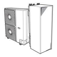
ERLQ004~008CA + EHVH/X04+08S18+26CB
Daikin Altherma – Low temperature split
4P384973-1A – 2016.02
▪ Make sure the return water to the heat pump does NOT exceed
55°C. To do so:
▪ Set the desired water temperature via the auxiliary boiler
controller to maximum 55°C.
▪ Install an aquastat valve in the return water flow of the
heatpump.
▪ Set the aquastat valve to close above 55°C and to open below
55°C.
▪ Install non-return valves.
▪ Make sure to only have one expansion vessel in the water circuit.
An expansion vessel is already premounted in the indoor unit.
▪ Install the digital I/O PCB (option EKRP1HB).
▪ Connect X1 and X2 (changeover to external heat source) on the
PCB to the auxiliary boiler thermostat.
▪ To setup the heat emitters, see "5.2Setting up the space heating/
cooling system"on page11.
Configuration
Via the user interface (quick wizard):
▪ Set the use of a bivalent system as external heat source.
▪ Set the bivalent temperature and hysteresis.
NOTICE
▪ Make sure the bivalent hysteresis has enough
differential to prevent frequent changeover between
indoor unit and auxiliary boiler.
▪ Because the outdoor temperature is measured by the
outdoor unit air thermistor, install the outdoor unit in the
shadow so that it is NOT influenced or turned ON/OFF
by direct sunlight.
▪ Frequent changeover may cause corrosion of the
auxiliary boiler. Contact the manufacturer of the
auxiliary boiler for more information.
Changeover to external heat source decided by an auxiliary
contact
▪ Only possible in external room thermostat control AND one
leaving water temperature zone (see "5.2 Setting up the space
heating/cooling system"on page11).
▪ The auxiliary contact can be:
▪ An outdoor temperature thermostat
▪ An electricity tariff contact
▪ A manually operated contact
▪ …
▪ Setup: Connect the following field wiring:
L
N
H
Com
A
K2AK1A
X2M
B
TI
K2AK1A
Indoor/Auto/Boiler
1 2 3 4 X Y
Indoor
B
TI
Boiler thermostat input
A Auxiliary contact (normal closed)
H Heating demand room thermostat (optional)
K1A Auxiliary relay for activation of indoor unit (field supply)
K2A Auxiliary relay for activation of boiler (field supply)
Indoor Indoor unit
Auto Automatic
Boiler Boiler
NOTICE
▪ Make sure the auxiliary contact has enough differential
or time delay to prevent frequent changeover between
indoor unit and auxiliary boiler.
▪ If the auxiliary contact is an outdoor temperature
thermostat, install the thermostat in the shadow so that
it is NOT influenced or turned ON/OFF by direct
sunlight.
▪ Frequent changeover may cause corrosion of the
auxiliary boiler. Contact the manufacturer of the
auxiliary boiler for more information.
5.4 Setting up the domestic hot water
tank
The DHW tank can be:
▪ Integrated in the indoor unit
▪ Installed standalone as option
5.4.1 System layout – Integrated DHW tank
Only for EHVH/X.
FHL1
FHL2
FHL3
M
UI
a b c d hh if
e
g
a Outdoor unit
b Indoor unit
c Heat exchanger
d Backup heater
e Pump
f Motorised 3‑way valve
g DHW tank
h Shut-off valve
i Collector (field supply)
FHL1...3 Underfloor heating
UI User interface
5.4.2 Selecting the volume and desired
temperature for the DHW tank
People experience water as hot when its temperature is 40°C.
Therefore, the DHW consumption is always expressed as equivalent
hot water volume at 40°C. However, you can set the DHW tank
temperature at a higher temperature (example: 53°C), which is then
mixed with cold water (example: 15°C).
Selecting the volume and desired temperature for the DHW tank
consists of:
1 Determining the DHW consumption (equivalent hot water
volume at 40°C).
2 Determining the volume and desired temperature for the DHW
tank.

 Loading...