Si12-714 Check
Service Diagnosis 225
6.1.14 Hall IC Check
Check No.16 1. Check the connector connection.
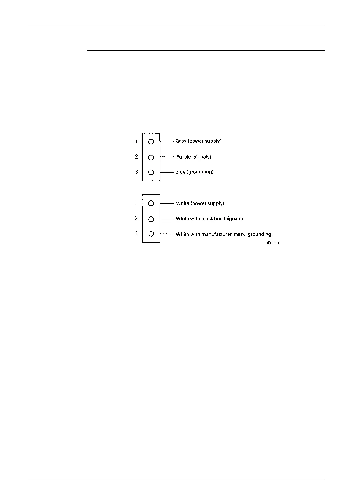
2. With the power ON, operation OFF, and the connector connected, check the following.
∗
Output voltage of about 5 V between pins 1 and 3.
∗
Generation of 3 pulses between pins 2 and 3 when the fan motor is operating.
Failure of (1)
Æ
faulty PCB
Æ
Replace the PCB.
Failure of (2)
Æ
faulty Hall IC
Æ
Replace the fan motor.
Both (1) and (2) result
Æ
Replace the PCB.
The connector has 3 pins, and there are two patterns of lead wire colors.
 Loading...