Operation manual
2
BRC315D7
Remote controller
4PW64949-1 – 10.2010
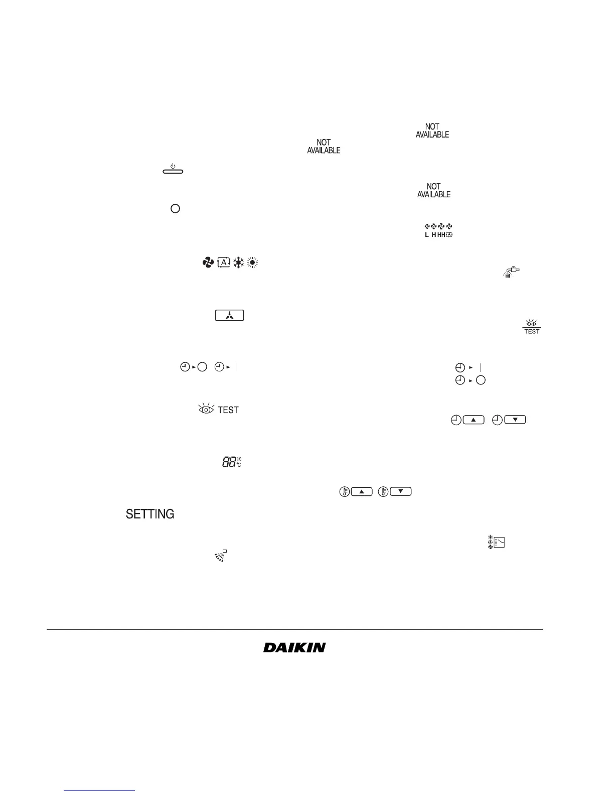
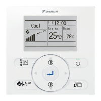
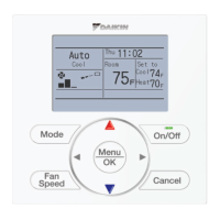
2. Name and function of switches and
icons
(Refer to figure 1)
1 ON/OFF BUTTON
Press the ON/OFF button to start or stop the system.
2 OPERATION LAMP
The operation lamp lights up during operation or
blinks if a malfunction occurs.
3 OPERATION MODE ICON
These icons indicate the current operation mode
(FAN, AUTOMATIC, COOLING, HEATING).
4 EXTERNAL CONTROL ICON
This icon indicates that another controller with higher
priority is controlling or disabling your installation.
5 ON/OFF TIMER ICON
This icon indicates that the ON/OFF timer is enabled.
6 INSPECTION REQUIRED
This icon indicates that inspection is required.
Consult your installer.
7 SET TEMPERATURE DISPLAY
This indicates the current set temperature of the
installation.
8 SETTING
Not used, for service purposes only.
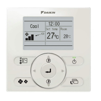
9 AIR FLOW DIRECTION ICON
This icon indicates the air flow direction (only for
installations with motorised air flow flaps).
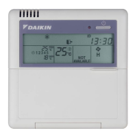
10 NOT AVAILABLE
is displayed whenever a non-installed option
is addressed or a function is not available.
When multiple indoor units are connected on the
same remote controller, " " will only be shown if
none of the connected units have this function.
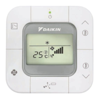
11 FAN SPEED ICON
This icon indicates the set fan speed.
12 AIR FILTER CLEANING TIME ICON
This icon indicates the air filter must be cleaned.
Refer to the manual of the indoor unit.
13 INSPECTION/TEST OPERATION BUTTON
Not used, for service purposes only.
14 ON/OFF TIMER BUTTON
This button enables or disables the ON/OFF timer.
15 TIME ADJUST BUTTON
These buttons are used to adjust the timer, when in
programming mode, to adjust the programmed action
time. Both buttons have an auto-repeat function.
16 TEMPERATURE ADJUST BUTTONS
These buttons are used to adjust the current setpoint
(16~32°C) (step = 1°C).
17 OPERATION CHANGE BUTTON
This button can be used to select the operation mode
of the installation (FAN, AUTOMATIC, COOLING,
HEATING).
This function is default not available. This function is
activated when the jumper (J8) wire is cut off. See
installation manual on how to cut off the jumper (J8).
,