22
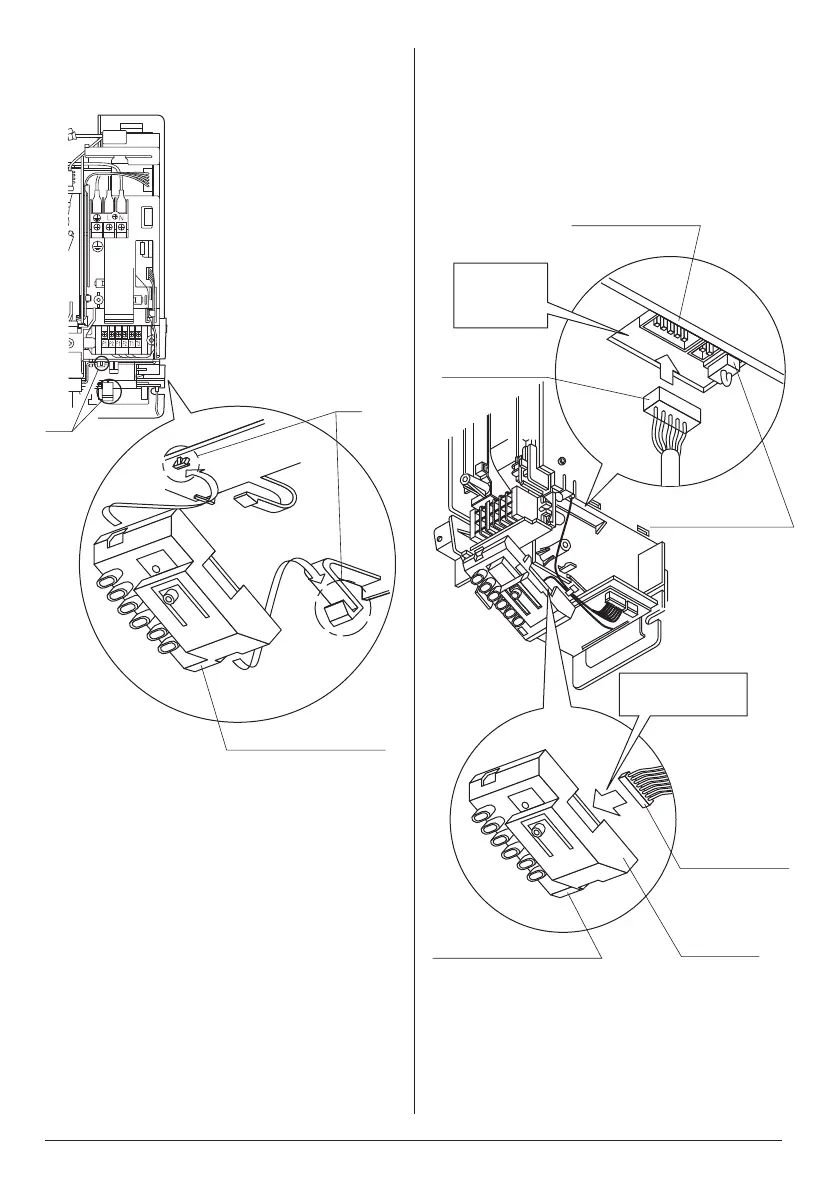
3. Attach the included receiver assembly (1)
to the 2 tabs on the indoor unit, as per the
gure.
Receiver assembly (1)
Ta b
Ta b
4. Connect the wire harnesses which were
connected to the transmission printed
circuit board (2) in step 1. as follows.
• Wire harness - long (3) to connector
X24A on the indoor unit printed circuit
board
• Wire harness - short (4) to connector
CN1/X1A on the receiver assembly (1)
Indoor unit printed
circuit board
Connector (X24A)
Wire harness -
long (3)
(Black)
Connect
rmlytothe
connector.
Wire harness -
short (4)
Connector
(CN1/X1A)
Receiver assembly (1)
Connectrmly
to the connector.
01_EN_4P457494-6L.indd 22 13/03/2019 11:07:50
 Loading...