12
Three Phase Models Only
Close the disconnect switch to energize control
transformer. Check primary and secondary (24V) of control
transformer.
The drive on the supply fan is typically set in the middle of
the RPM range. The drive motor sheave pitch diameter is
eld adjustable for the required airow. Upon completion
of the air ow balancing, we recommend replacing the
variable pitched motor sheave with a properly-sized xed
sheave. A matching xed sheave will provide longer belt
and bearing life and vibration free operation. Initially, it
is best to have a variable pitched motor sheave for the
purpose of airow balancing, but once the balance has
been achieved, xed sheaves maintain alignment and
minimize vibration more eectively. Refer to the following
“Drive Adjustments” section.
When the nal adjustments are complete, the current
draw of the motor should be checked and compared to
the full load current rating of the motor. The amperage
must not exceed the service factor stamped on the motor
nameplate.
If an economizer is installed, check the unit operating
balance with the economizer at full outside air and at
minimum outside air. Upon completion of the air ow
balancing, we recommend replacing the variable pitched
motor sheave with a properly-sized xed sheave. A
matching xed sheave will provide longer belt and bearing
life and vibration free operation. Initially, it is best to have
a variable pitched motor sheave for the purpose of airow
balancing, but once the balance has been achieved, xed
sheaves maintain alignment and minimize vibration more
eectively.
Check that fan rotates clockwise when viewed from the
drive side of unit and in accordance with rotation arrow
shown on blower housing. If it does not, reverse any two
incoming power cables at Single Point Power Block. In this
case, repeat bearing check.
Do not attempt to change load side wiring. Internal wiring
assures all motors and compressors will rotate in correct
direction once evaporator fan motor rotation check has
been made.
Make preliminary check of evaporator fan ampere draw
and verify that motor nameplate amps are not exceeded. A
nal check of amp draw should be made upon completion
of air balancing of the duct system.
Actual RPM’s must be set and veried with a tachometer
or strobe light. Refer to Appendex A for basic unit fan
RPM. Refer also to “Airow” section of this manual. With
disconnect switch open, disconnect thermostat wires
from terminals Y and W. This will prevent heating and
mechanical cooling from coming on. Place a jumper wire
across terminals R and G at TB1 terminal block. Close
disconnect switch; evaporator fan motor will operate so
RPM can be checked.
Refer to “Motor Sheave Adjustments” section.
Prior to energizing any fans, check and make sure that all
setscrews are tight so that bearings are properly secured
to shafts.
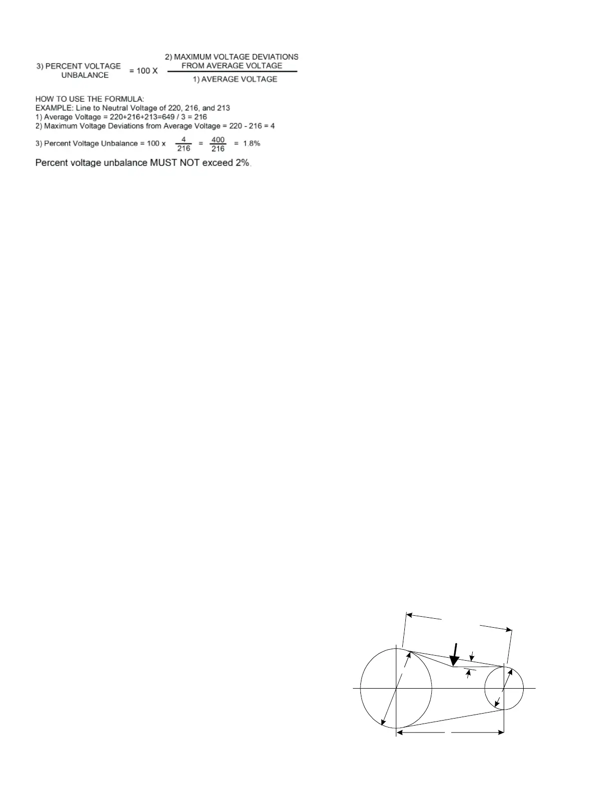
Correct belt tension is very important to the life of your belt.
Too loose a belt will shorten its life; too tight, premature
motor and bearing failure will occur. Check your belt
drive for adequate “run-in” belt tension by measuring the
force required to deect the belt at the midpoint of the
span length. Belt tension force can be measured using
a belt tension gauge, available through most belt drive
manufacturers.
S
P
A
N
L
E
N
G
T
H
t
*
D
E
F
L
E
C
T
I
O
N
F
O
R
C
E
h
C
d
H
D



 To Next Page