13
t = Span length, inches
C = Center distance, inches
D = Larger sheave diameter, inches
d = Smaller sheave diameter, inches
h = Deection height, inches
DBH/DBC090*V 2.6 to 3.6 4.5+/-.5 5.5+/-.5 1/4+/-1/16
DBH/DBC090*S 3.0 to 4.0 4.5+/-.5 5.5+/-.5 1/4+/-1/16
DBH/DBC102*V 2.6 to 3.6 4.5+/-.5 5.5+/-.5 1/4+/-1/16
DBH/DBC102*S 3.0 to 4.0 4.5+/-.5 5.5+/-.5 1/4+/-1/16
DBH/DBC120*V 2.6 to 3.6 4.5+/-.5 5.5+/-.5 1/4+/-1/16
DBH/DBC120*S 3.0 to 4.0 4.5+/-.5 5.5+/-.5 1/4+/-1/16
DBC150*V 3.0 to 4.0 4.5+/-.5 5.5+/-.5 1/4+/-1/16
DBC150*S 4.2 to 5.2 4.5+/-.5 5.5+/-.5 1/4+/-1/16
When new V-belts are installed on a drive the initial
tension will drop rapidly during the rst few hours. Check
tension frequently during the rst 24 hours of operation.
Subsequent re-tensioning should fall between the minimum
and maximum force. To determine the deection distance
from the normal position, use a straightedge or stretch a
cord from sheave to sheave to use as a reference line. On
multiple belt drives, an adjacent undeected belt can be
used as a reference.
The driving and driven sheaves should be in alignment with
each other and the shafts parallel.
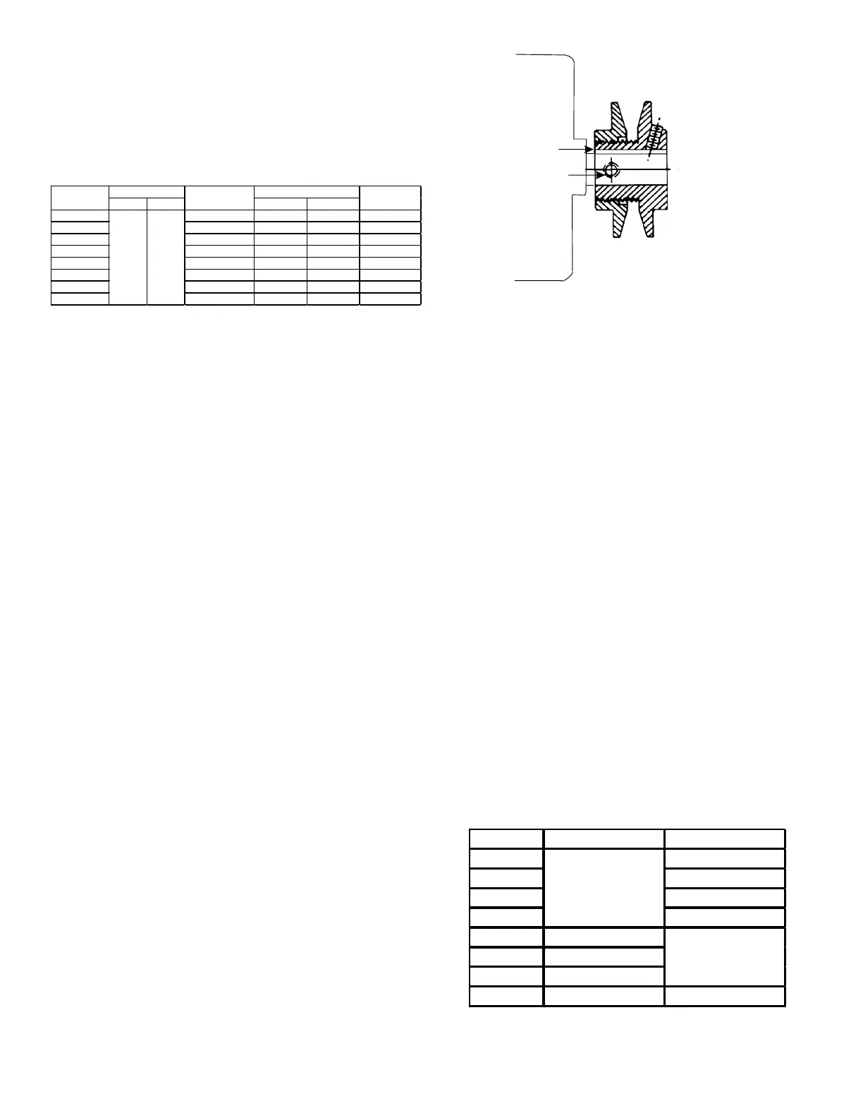
1. Loosen set screw “B” using a 5/32” Allen key.
2. Making half or full turns from closed position, adjust
sheave pitch diameter for desired speed. DO NOT
OPEN MORE THAN SIX FULL TURNS.
3. Tighten set screw “B” securely over at.
4. Carefully put on belts and adjust belt tension. DO
NOT FORCE BELTS OVER GROOVES.
5. Ensure all keys are in place and the set screws tight
before starting drive. Recheck set screws and belt
tension after 24 hours service.
Make preliminary check of evaporator fan ampere draw
and verify that motor nameplate amps are not exceeded. A
nal check of amp draw should be made upon completion
of air balancing of the duct system (see Appendix B).
Heat pump units are equipped with thermal expansion
valves.
Ensure the hold-down bolts on the compressor are secure
and have not vibrated loose during shipment. Check
that the vibration grommets have been installed and
visually check all piping for damage and leaks and repair
if necessary. The entire system has been factory charged
and tested, making it unnecessary to eld charge. Factory
refrigerant charge is shown on the unit’s nameplate.
To conrm charge levels or, if a leak occurs and charge
needs to be added to the system, it is recommended to
evacuate the system and recharge refrigerant to the unit’s
nameplate specications. This unit has been rated in
the cooling mode at the AHRI rated conditions of: indoor
(80°F db/67°F wb) and outdoor (95°F db). While operating
at this condition, the superheat (measured at the suction
service port located near the compressor) or the subcool
(measured at the outdoor liquid line port) should be within
the range given in the following table.
DBC090* 11 to 15
DBC102* 10 to 14
DBC120* 10 to 14
DBC150* 11 to 17
DBH090* 3 to 7
DBH102* 13 to 17
DBH120* 9 to 13
DBH150* 10 to 14 20 to 25



 To Next Page