9
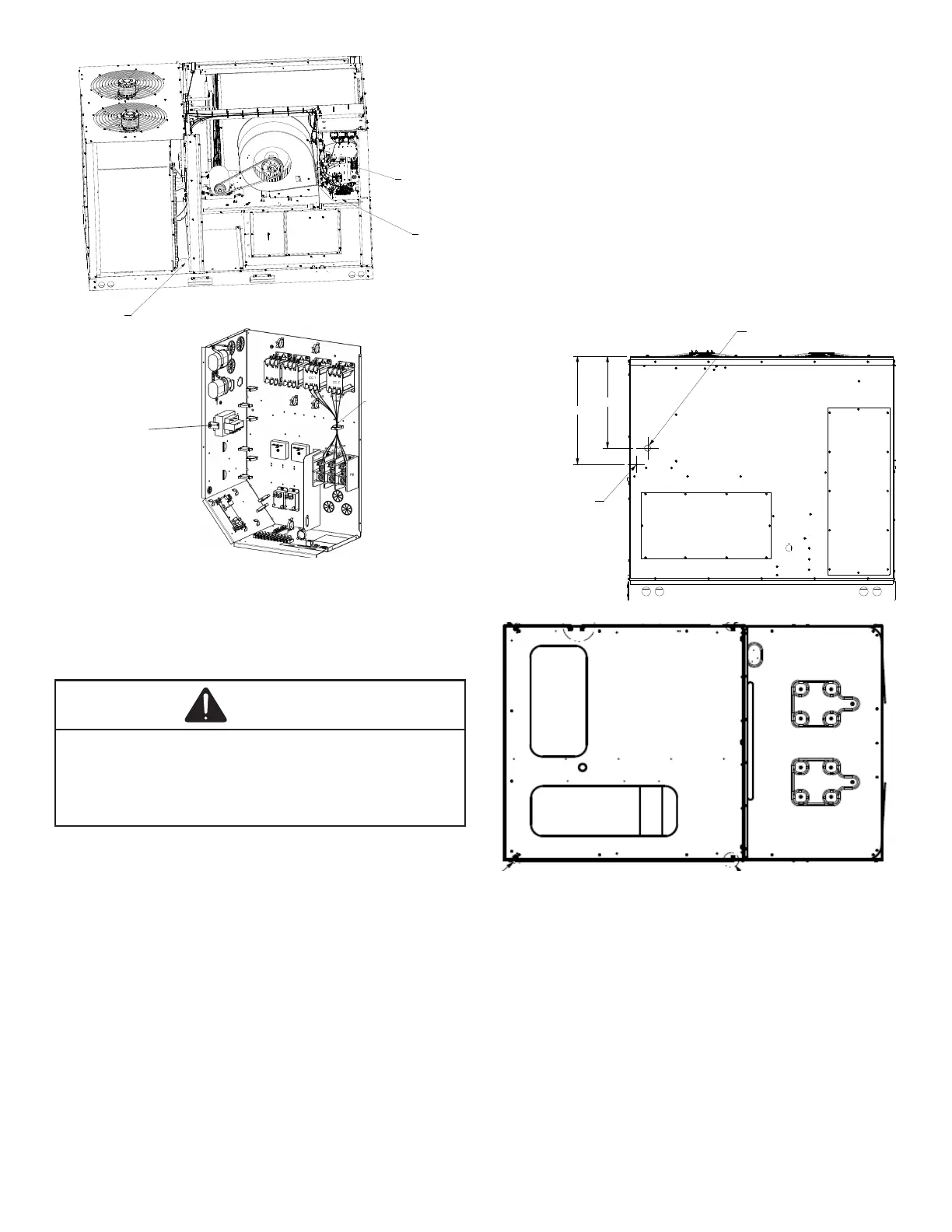
CONTROL BOX
NOTE: CHECK TRANSFORMER TO
MATCH THE CORRECT VOLTAGE TAP
WITH LINE VOLTAGE
LINE VOLTAGE L1, L2, L3
WARNING
Areas Without Convenience Outlet
It is recommended that an independent 115V power source
be brought to the vicinity of the roof top unit for portable
lights and tools used by the service mechanic.
Main power and low voltage wiring may enter the unit
through the condenser end of unit or through the roof curb.
Install conduit connectors at the desired entrance locations.
External connectors must be weatherproof. All holes in the
unit base must be sealed (including those around conduit
nuts) to prevent water leakage into building. All required
conduit and ttings are to be eld supplied.
Supply voltage to roof top unit must not vary by more than
10% of the value indicated on the unit data plate. Phase
voltage unbalance must not exceed 2%. Contact your
local power company for correction of improper voltage or
phase unbalance.
20-3/4"
24.4"
LOW VOLTAGE ENTRANCE
HIGH VOLTAGE ENTRANCE
(REMOVE PLUG)
SUPPLY
RETURN
1. A 24V thermostat must be installed for unit operation.
2. Locate thermostat or remote sensor in the conditioned
space where it will sense average temperature. Do
not locate the device where it may be directly exposed
to supply air, sunlight or other sources of heat. Follow
installation instructions packaged with the thermostat.
3. Use #18 AWG wire for 24V control wiring runs not
exceeding 75 feet. Use #16 AWG wire for 24V control
wiring runs not exceeding 125 feet. Use #14 AWG
wire for 24V control wiring runs not exceeding 200
feet. Low voltage wiring may be National Electrical
Code (NEC) Class 2 where permitted by local codes.