14
The gas line installation must comply with local codes, or
in the absence of local codes, with the latest edition of the
National Fuel Gas Code NFPA 54 / ANSI Z223.1.
Pressure= .50 PSIG or less and Pressure Drop of 0.3" W.C.
(Based on 0.60 Specific Gravity Gas)
Nominal Black Pipe Size (inches)
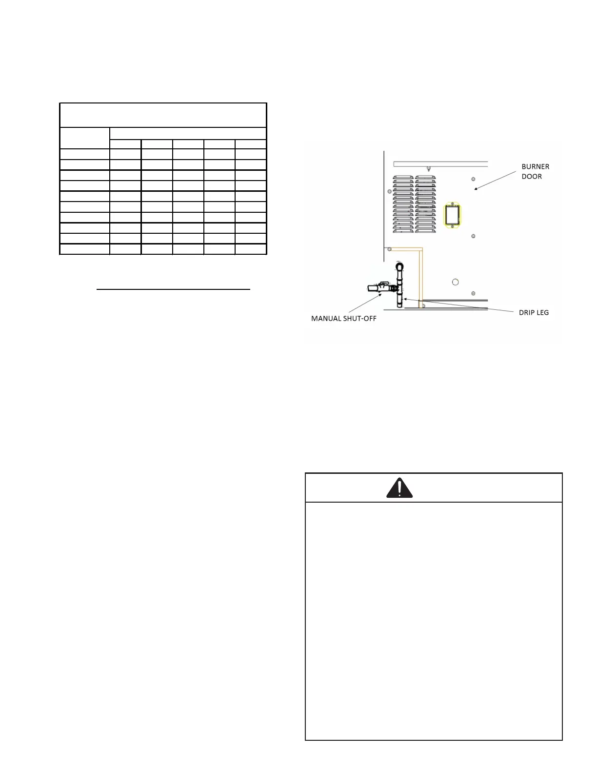
Refer to the Proper Piping Practice drawing for the general
layout at the unit. The following rules apply:
1. Use black iron pipe and ttings for the supply piping.
The use of a ex connector and/or copper piping is
permitted as long as it is in agreement with local
codes.
2. Use pipe joint compound on male threads only. Pipe
joint compound must be resistant to the action of the
fuel used.
3. Use ground joint unions.
4. Install a drip leg to trap dirt and moisture before it can
enter the gas valve. The drip leg must be a minimum
of three inches long.
5. Use two pipe wrenches when making connection to
the gas valve to keep it from turning.
6. Install a manual shut-o valve in a convenient location
(within six feet of unit) between the meter and the unit.
7. Tighten all joints securely.
8. The unit must be connected to the building piping by
one of the following methods:
• Rigid metallic pipe and ttings
• Semirigid metallic tubing and metallic ttings
(Aluminum alloy tubing must not be used in
exterior locations).
• Listed gas appliance connectors used in
accordance with the terms of their listing
that are completely in the same room as the
equipment. Always use a new listed connector.
• In the prior two methods above the connector
or tubing must be protected from physical
and thermal damage. Aluminum alloy tubing
and connectors must be coated to protect
against external corrosion when in contact with
masonry, plaster or insulation or are subject to
repeated wettings by liquids (water - not rain
water, detergents or sewage).
CAUTION