20
Actual RPM’s must be set and veried with a tachometer
or strobe light. Refer to Appendex A for basic unit fan
RPM. Refer also to “Airow” section of this manual. With
disconnect switch open, disconnect thermostat wires
from terminals Y and W. This will prevent heating and
mechanical cooling from coming on. Place a jumper wire
across terminals R and G at TB1 terminal block. Close
disconnect switch; evaporator fan motor will operate so
RPM can be checked.
Make preliminary check of evaporator fan ampere draw
and verify that motor nameplate amps are not exceeded. A
nal check of amp draw should be made upon completion
of air balancing of the duct system (see Appendix B).
The rst step in checking out the gas-red furnace is to test
the gas supply piping to the unit for tightness and purge the
system of air using methods outlined in the latest edition of
the National Fuel Gas Code ANSI Z223.1 / NFPA 54. Verify
that the disconnect switch is in the “OFF" position. A soapy
water solution should be used to check for gas leaks.
Since the unit is subject to considerable jarring during
shipment, it is extremely important that all gas connections
and joints be tested for tightness. Gas piping downstream
from the unit inlet should be checked for leaks during the
subsequent sequence check.
The supply gas pressure should be adjusted to 7.0” w.c.
on natural gas and 11.0” on LP gas with the gas burners
operating. If there is more than one unit on a common gas
line, the pressures should be checked with all units under
full re. A supply pressure tap is provided on the upstream
side of the gas valve. A manifold pressure tap is provided
on the manifold. The normal manifold pressure for full input
is 3.5” w.c. on natural gas and 10.0” w.c. for propane gas.
Minimum gas supply pressure is 5.5” w.c. for natural gas
and 11.0” for propane gas. In order to obtain rating, gas
supply pressure must be 11.0” w.c. for propane gas.
The pressure regulator on LP gas models is adjusted for
10.0” w.c. manifold pressure and is intended to prevent
over-ring only. Do not attempt adjustment of the built-in
pressure regulator unless the supply pressure is at least
7.0” w.c. on natural gas or 14.0” w.c. on propane gas.
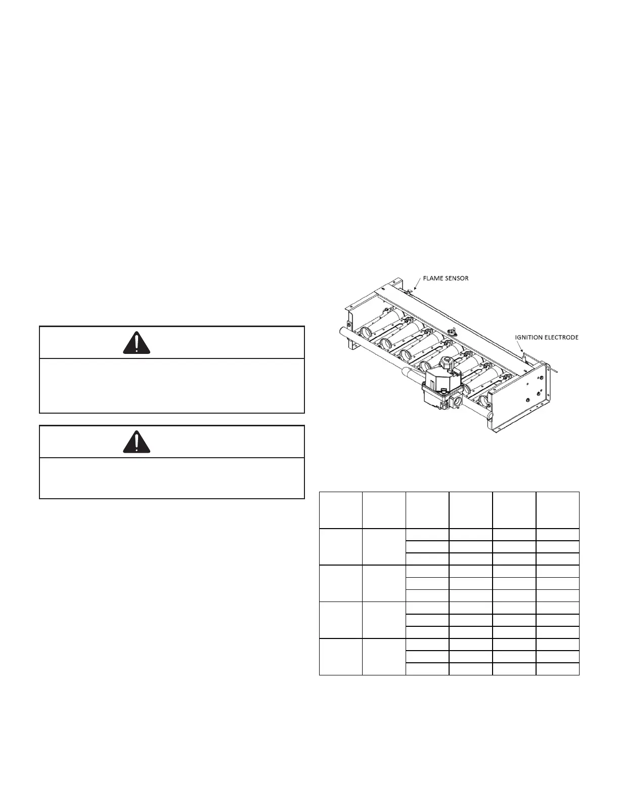
Check the location of the ignition electrode and the ame
sensor for correct gap setting.
Ton Model
High Fire
Rate
Btu/Hr
No. of
Burners
N.G.
Orfice
Drill #
L.P. Orfice
Drill #
130,000 5 41 54
180,000 6 37 53
225,000 7 36 52
130,000 5 41 54
180,000 6 37 53
225,000 7 36 52
130,000 5 41 54
180,000 6 37 53
240,000 7 36 52
130,000 5 41 54
180,000 6 37 53
240,000 7 36 52
7.5
8.5
10
12.5
DFG102
DFG090
DFG120
DFG150