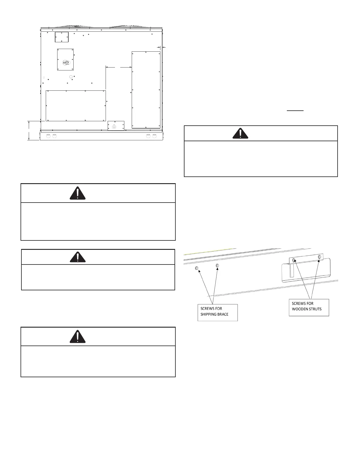
9
9-1/2"
13"
1"
SUPPLY
13.9" X 28.3"
RETURN
12.5" X 36.4"
CAUTION
• Unit must be lifted by the four lifting holes located at
the base frame corners.
• Lifting cables should be attached to the unit with
shackles.
• The distance between the crane hook and the top of
the unit must not be less than 60".
• Two spreader bars must span over the unit to prevent
damage to the cabinet by the lift cables. Spreader
bars must be of sucient length so that cables do
not come in contact with the unit during transport.
Remove wood struts mounted beneath unit base
frame before setting unit on roof curb. These struts
are intended to protect unit base frame from fork lift
damage. Removal is accomplished by extracting the
sheet metal retainers and pulling the struts through
the base of the unit. Refer to rigging label on the unit.
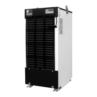
• Your unit may be equipped with a steel shipping brace
located underneath the unit (under compressors). If
installing on a roof curb, the brace be removed.
Follow the following instructions for removal.
CAUTION
1. Remove wooden struts per installation instructions.
These are the struts that are located in the fork holes
and are used to protect the unit from damage while
lifting with forks.
2. Locate and remove the four (4) screws that attach the
shipping brace to the side rails. There will be two (2)
screws on each side of the unit. See following gure.
3. Lift unit per the “Rigging Details” section of the
installation instructions, observing all warnings and
cautions. Lift the unit high enough o the ground to
reach under and grasp the shipping brace.
4. Rotate the brace by tapping the ends until the brace
falls free from the unit.
5. Dispose of the brace appropriately.