16
3. These units are designed for either natural or
propane (LP) gas and are specically constructed at
the factory for only one of these fuels. The fuels are
NOT interchangeable. However, the furnace can be
converted in the eld from natural gas to LP gas with
the appropriate factory kit (see unit Technical Manual
for the appropriate kit). Only a qualied contractor,
experienced with natural and propane gas systems,
should attempt conversion. Kit instructions must
be followed closely to assure safe and reliable unit
operation.
4. With all units on a common line operating under
full re, natural gas main supply pressure should
be adjusted to approximately 7.0” w.c., measured
at the unit gas valve. If the gas pressure at the
unit is greater than 10.5” w.c., the contractor must
furnish and install an external type positive shut o
service pressure regulator. The unit will not function
satisfactorily if supply gas pressure is less than 5.5”
w.c. or greater than 10.5” w.c..
5. With all units on a common line operating under
full LP gas main supply pressure should be at least
11.0” w.c. and must be no greater than 14.0” w.c.,
measured at the unit gas valve. Unit will not function
satisfactorily if supply gas pressure is less than 11.0”
w.c. or greater than 14.0” w.c..
6. All pipe connections should be sealed with a pipe
thread compound, which is resistant to the fuel used
with the furnace. A soapy water solution should be
used to check all joints for leaks. A 1/8” NPT plugged
tap is located on the entering side of the gas valve for
test gauge connection to measure supply (main) gas
pressure. Another 1/8” tap is provided on the side of
the manifold for checking manifold pressure.
CAUTION
7. There must be no obstruction to prevent the ow of
combustion and ventilating air. A vent stack is not
required and must never be used. The power venter
will supply an adequate amount of combustion air
as long as the air passageways are kept free of any
obstructions and the recommended external unit
clearances are maintained.
The supply duct from the unit through a wall may be
installed without clearance. However, minimum unit
clearances must be maintained (see “Clearances" section).
The supply duct should be provided with an access panel
large enough to inspect the air chamber downstream of
the heat exchanger. A cover should be tightly attached to
prevent air leaks.
Ductwork dimensions are shown in the roof curb
installation manual.
If desired, supply and return duct connections to the unit
may be made with exible connections to reduce possible
unit operating sound transmission.
The inductor motor on DFG units is a dual voltage motor. It
is factory wired for 230 volts. If eld supply power is 208V,
the installer must swap the connections of the black and
red leads (located in the blower compartment) to ensure
correct inductor motor operation.
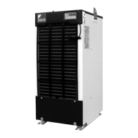
A 3/4" female NPT drain connection is supplied on the
end of the unit and bottom of the drain pan for condensate
piping. An external trap must be installed for proper
condensate drainage. Hand tighten drain tting to the drain
connection.