22
2. With the unit operating, time the smallest dial on the
meter for one complete revolution. If this is a 2 cubic
foot dial, divide the seconds by 2; if it is a 1 cubic foot
dial, use the seconds as is. This gives the seconds
per cubic foot of gas being delivered to the unit.
3. INPUT=GAS HTG VALUE x 3600 / SEC. PER CUBIC
FOOT
Natural gas with a heating value of 1000 BTU
per cubic foot and 34 seconds per cubic foot as determined
by Step 2, then:
Input = 1000 x 3600 / 34 = 106,000 BTU per Hour.
Adjust input rate by varying the adjustment of the gas
pressure regulator on the gas valve. All adjustments
must be made with furnace operating at high re and at
normal operating temperature. A manometer should be
connected to the gas valve to verify pressure is within
the specied range (see following gures for manometer
connections). Clockwise rotation of the pressure regulator
screw increases pressure and gas ow rate. Turn screw
counterclockwise to decrease pressure and gas ow rate.
After adjustment the furnace temperature rise must be
within the range specied on the unit data plate.
O
N
O
F
F
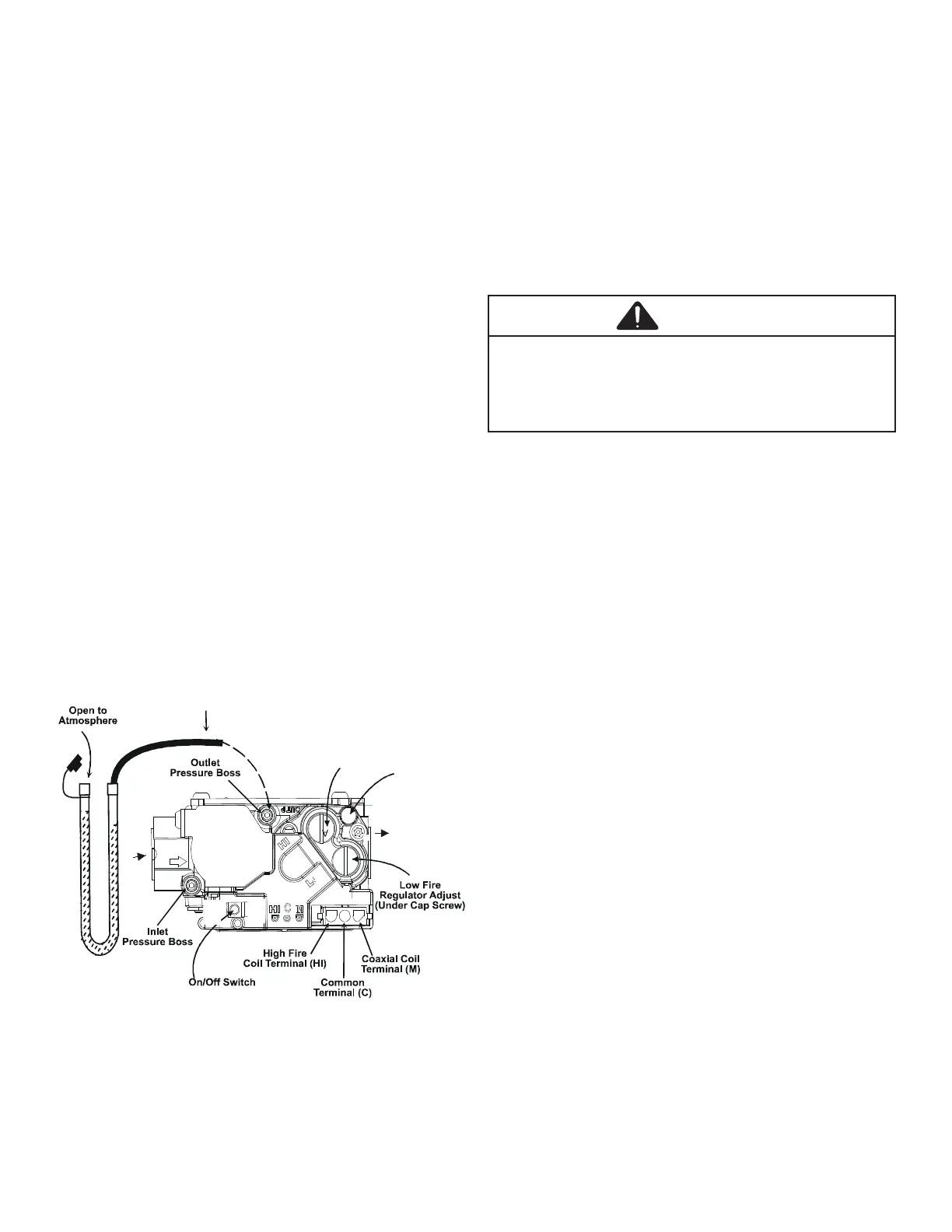
To connect manometer to gas valve:
1. Back outlet pressure tap screw (inside inlet pressure
boss) out one turn (counterclockwise, not more than
one turn).
2. Attach a hose and manometer to the outlet pressure
boss of the valve.
To remove manometer from gas valve:
1. Remove manometer hose from outlet pressure boss.
2. Turn outlet pressure tap screw in to seal pressure port
(clockwise, 7 in-lb. minimum).
3. Turn on electrical power and gas supply to the
system.
4. Turn on system power and energize valve.
5. Using a leak detection solution or soap suds, check
for leaks at pressure boss screw. Bubbles forming
indicate a leak. SHUT OFF GAS AND FIX ALL LEAKS
IMMEDIATELY.
CAUTION
6. Relight all other appliances turned o in step 1 of gas
input check. Be sure all pilot burners are operating.
Flames should be stable, soft and blue (dust may cause
orange tips but they must not be yellow) and extending
directly outward from the burner without curling, oating or
lifting o.
Verify that the alignment of the NOx screens is at 6
o’ clock. In jurisdictions that do not require low NOx
emissions, NOx screens may be removed.
Check the temperature rise through the unit by placing
thermometers in supply and return air registers as close
to the unit as possible. Thermometers must not be able to
sample temperature directly from the unit heat exchangers,
or false readings could be obtained.
1. All registers must be open; all duct dampers must be
in their nal (fully or partially open) position and the
unit operated for 15 minutes before taking readings
2. The temperature rise must be within the range
specied on the rating plate.
With a properly designed system, the proper amount of
temperature rise will normally be obtained when the unit
is operated at rated input with the recommended blower
speed.
If the correct amount of temperature rise is not obtained, it
may be necessary to change the blower speed. A higher
blower speed will lower the temperature rise. A slower
blower speed will increase the temperature rise.