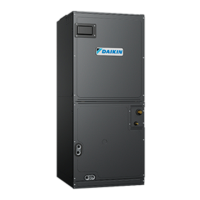
DMVT***P1400**
AIR HANDLERS INSTALLATION &
OPERATING INSTRUCTIONS
© 2022-2023
www.daikincomfort.com
19001 Kermier Rd., Waller, TX 77484
P/N: IOD-4040B Date: February 2023
NOTE: SPECIFICATIONS AND PERFORMANCE DATA LISTED HEREIN
ARE SUBJECT TO CHANGE WITHOUT NOTICE
NOTICE: IF AN “Ec” error is encountered on startup, verify that the elec-
tric heater DIP switches have been set to the appropriate heater size. See
Contents
1 Important Safety Instructions .................................... 3
2 Shipping Inspection ................................................... 3
2.1 Parts ....................................................................... 3
2.2 Handling ................................................................. 3
2.3 Shipping Material Removal..................................... 3
2.3.1 Blower Support Bracket Removal ....................... 3
3 Codes & Regulations ................................................. 3
4 Replacement Parts ..................................................... 3
5 Pre-Installation Considerations ............................... 3
5.1 Preparation ............................................................. 3
5.2 System Matches ..................................................... 3
5.3 Interconnecting Tubing ........................................... 3
5.4 Clearances ............................................................. 3
5.5 Horizontal Applications ........................................... 4
6 Installation Location ................................................... 4
4
...................... 5
6.3 Horizontal Right Installation ................... 5
6.4 Humid Environment Installations ............................ 5
6.4.1 All Installations – Humid Environments ............... 5
5
6.4.1.3 Horizontal Installations – Humid Environments 5
7 Refrigerant Lines ........................................................ 6
7.1 Tubing Size ............................................................. 6
7.2 Tubing Preparation ................................................. 6
7.3 Tubing Connections ................................................ 7
7.4 Thermal Expansion Valve System Adjustment ....... 9
8 Condensate Drain Lines ........................................... 10
9 Ductwork .................................................................... 11
9.1 Return Ductwork .................................................... 11
10 Return Air Filters ..................................................... 11
11 Electric Heat ............................................................. 11
12 Electrical and Control Wiring ................................. 12
12.1 Building Electrical Service Inspection .................. 12
12.2 Wire Sizing .......................................................... 12
............ 12
12.4 Electrical Connections – Supply Voltage ............. 13
RECOGNIZE SYMBOL THIS
AS A SAFETY PRECAUTION
WARNING
DO NOT BYPASS SAFETY DEVICES.
WARNING