9 | Electrical installation
Installer reference guide
80
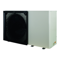
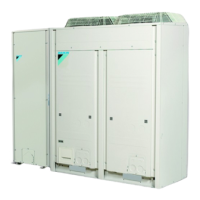
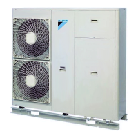
EWAA011~016DA + EWYA009~016DA
Packaged air-cooled water chillers
and packaged air to water heat pumps
4P620242-1 – 2020.06
Item Description
WLAN cartridge See:
▪ Installation manual of the WLAN cartridge
▪ Installer reference guide
—
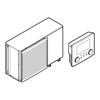
[D] Wireless gateway
Flow switch See installation manual of the flow switch
Wires: 2×0.5mm²
—
Location extra components
The following illustration shows the location of the extra components that you
need to install on the outdoor unit when using certain option kits.
a Flow switch (EKFLSW1)
b Demand PCB (A8P: EKRP1AHTA)
c Digital I/O PCB (A4P: EKRP1HBAA)
d Smart grid relay kit (EKRELSG)
9.2.1 To connect the electrical wiring to the outdoor unit
1 Open the service cover. See "To open the outdoor unit"[461].
2 Strip insulation (20mm) from the wires.
a Strip wire end to this point
b An excessive strip length may cause electrical shock or leakage
3 Insert the cables at the back of the unit, and route them through the unit to
the appropriate terminal blocks.
 Loading...