English 16
10. TEST OPERATION
Refer to the section of “FOR THE FOLLOWING ITEMS, TAKE SPECIAL CARE DURING CON-
STRUCTION AND CHECK AFTER INSTALLATION IS FINISHED” .
• After finishing the construction of refrigerant piping, drain piping, and electric wiring, conduct test operation
accordingly to protect the unit.
1. HOW TO TEST OPERATION
1 Open the gas side stop valve.
2 Open the liquid side stop valve.
3 Electrify crank case heater for 6 hours (Not required in case of a unit exclusively designed for cooling
only).
4 Set to cooling operation with the remote controller and start operation by pushing ON/OFF button
().
5 Press INSPECTION/TEST OPERATION button ( ) 4 times (2 times for wireless remote controller)
and operate at Test Operation mode for 3 minutes.
6 Push AIR FLOW DIRECTION ADJUST button ( ) to make sure the unit is in operation.
7 Press INSPECTION/TEST OPERATION button ( ) and operate normally.
8 Confirm function of unit according to the operation manual.
PRECAUTIONS
• Refer to the diagnoses below if the unit does not operate properly.
• After completing the test run, press the INSPECTION/TEST OPERATION button once to put the unit
in inspection mode, and make sure the malfunction code is “00” (=normal).
If the code reads anything other than “00”, refer to the malfunction diagnoses below.
2. HOW TO DIAGNOSE FOR PROBLEMS
With the power on. Troubles can be monitored on the remote controller or the LED’s on the PC
board of the indoor unit.
䡵Trouble shooting with the display on the liquid crystal display remote controller.
1 With the wired remote controller. (NOTE 1)
When the operation stops due to trouble, operation lamp flashed, and “ ” and the error code are
indicated on the liquid crystal display . In such a case, diagnose the fault contents by referning to
the table on the Error code list it case of group control, the unit No. is displayed so that the indoor
unit no with the trouble can be recognized. (NOTE 2)
2 With the wireless remote controller.
(Refer also to the operation manual attached to the wireless remote controller)
When the operation stops due to trouble. the display on the indoor unit flashes. In such a case, diag-
nose the fault contents with the table on the Error code list looking for the error code which can be
found by following procedures. (NOTE 2)
(1) Press the INSPECTION /TEST OPERATION button, “ ” is displayed and “ 0 ” flashes.
S
M
S
S
M
Factory setting
Only one remote controller
needs to be changed
if factory settings have
remained untouched.
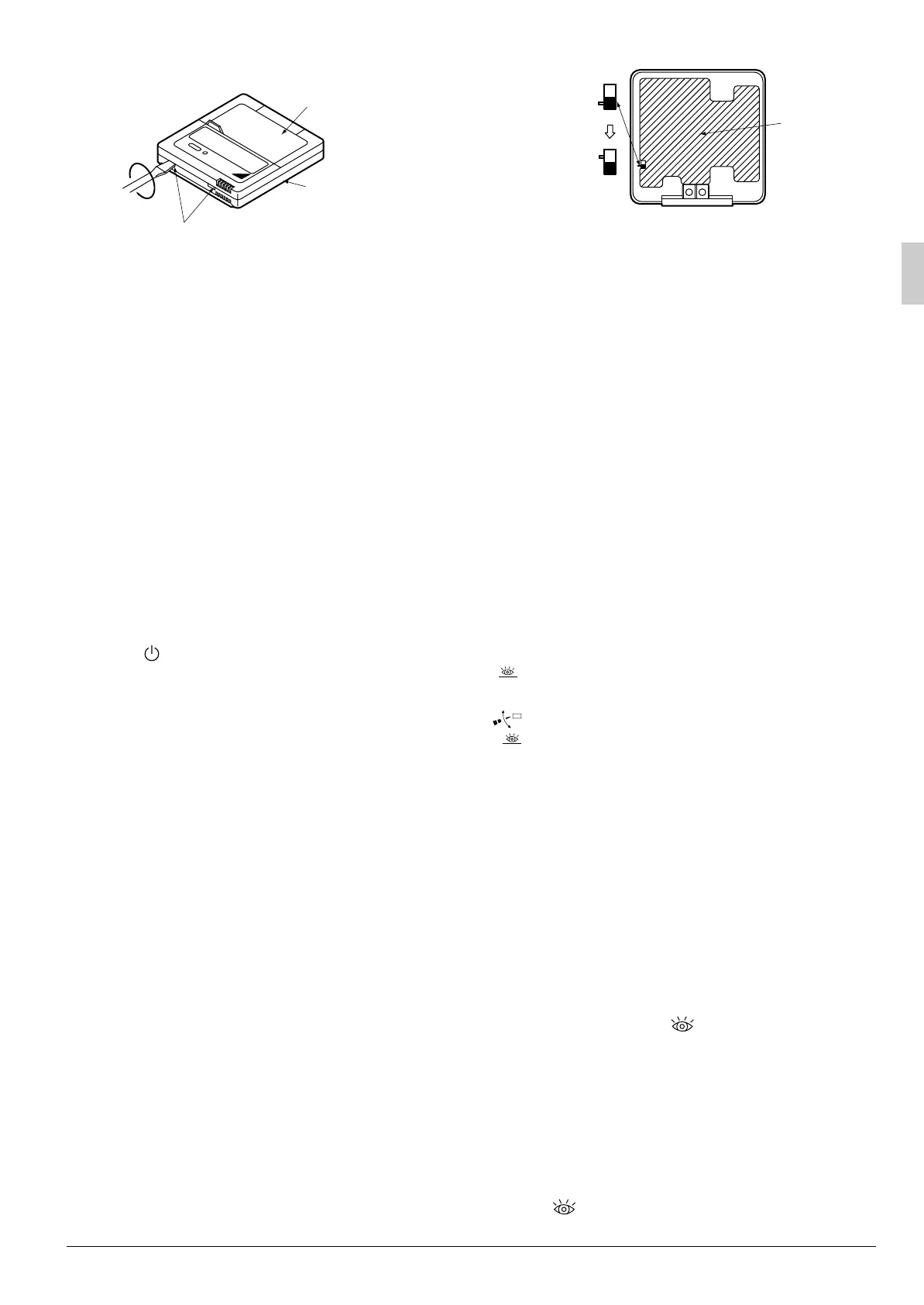
Remote
controller
PC board
Fig. 21
Lower part of
remote controller
Upper part of
remote controller
Fig. 20
Insert the screwdriver here and gently
work off the upper part of remote controller.
TEST
TEST
01_EN_3P184443-2.fm Page 16 Monday, July 3, 2006 3:14 PM
 Loading...