Combination Fan and Limit Control
The fan limit control is a hydraulic action type with a remote
sensing element and connecting capillary tube. The sensing
element is locked into a bracket located on one of the heat
exchanger tubes about halfway toward the back of the furnace,
on the side away from the blower. One corner of the bracket is
bent aside to remove the element.
Normal setting of the FAN control: Fan ON=125°F, Fan
OFF=100°F.
The LIMIT control must never be set higher than the
temperature listed below. If the burner is shutting o on high
limit at these settings, it indicates that there is a problem with
the furnace not getting enough air or it is being overred.
Table 5: Limit Control Set Points
BURNER
MODEL
LIMIT
CONTROL
SET POINT
BURNER
MODEL
LIMIT
CONTROL
SET POINT
020 215 079 181
025 160 080 229
032 196 100 170
040 154 110 222
050 229 140 168
064 185 150 194
065 232 200 151
Replacing “White Rogers” Fan
Limit Controller with “Antunes”
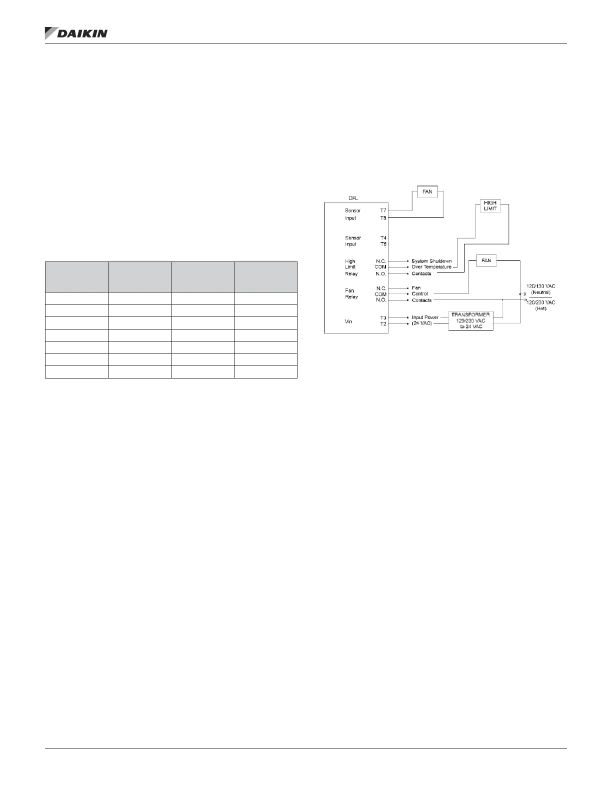
Wire 24 VAC input power to terminals T2 and T3. Wire
temperature sensor from the secondary tubes at the heat
exchanger to terminals T7 and T8. Connect N.C and COM
wires for internal fan and high limit relays
Figure 19: Antunes
®
Fan Limit Controller
IM 684-6 • ROOFTOP SYSTEMS 22 www.DaikinApplied.com



 To Next Page