Electrical
WARNING
Improper installation, adjustment, alteration, service or maintenance
can cause property damage, severe personal injury or death. Read the
installation, operating and maintenance instructions thoroughly before
installing or servicing this equipment.
If you smell gas:
1. Open Windows and ventilate area thoroughly.
2. Don’t touch electrical switches.
3. Eliminate open ames, pilot lights, arcing or sparking
equipment, or other sources of ignition.
4. Evacuate the area.
5. Immediately call your gas supplier from a different area.
Do not use and store gasoline or other ammable vapors or liquids in open
containers near this appliance or in areas sharing ventilation with it..
The Daikin burner receives its electrical power from the main
unit control panel. No additional power wiring must be routed
to the burner. The sequencing of the burner is also controlled
through this panel and therefore is factory wired. No additional
wiring will be required. Note that Models 150 through 200
furnaces require reassembly of some electrical connections as
the burner is removed for shipment.
Gas Pressure Requirements
The pressure furnished to the appliance gas pressure regulator
immediately before the main gas valve must not exceed 13.9
in. W.C. or be below the minimum specied in Table 10 on
page 36, Column 14. When the supply pressure is above
13.9 in. W.C., a high pressure regulator must precede the
appliance gas pressure regulator. The inlet gas pressure
must not exceed the maximum pressure rating of the high
pressure regulator, and the outlet pressure must furnish gas
to the appliance pressure regulator within the pressure range
mentioned above.
Gas Piping
The connection size at the burner is shown in Table 10 under
columns 17 and 18. Gas piping must be sized to provide the
minimum required pressure at the burner when the burner is
operating at maximum input. Consult your local utility on any
questions on gas pressure available, allowing piping pressure
drops, and local piping requirements.
Install all piping in accordance with the National Fuel Gas Code
(ANSI Z223.1), (NFPA 54-1999) and any applicable local codes.
The proper size piping must be run from the meter to the
gas burner without reductions. Undersized piping will result
in inadequate pressure at the burner. The pressure will be at
its lowest when it is needed the most, at times of maximum
demand. Therefore, it can cause intermittent hard-to-nd
problems because the problem may have left before the
service technician has arrived. Avoid the use of bushings
wherever possible.
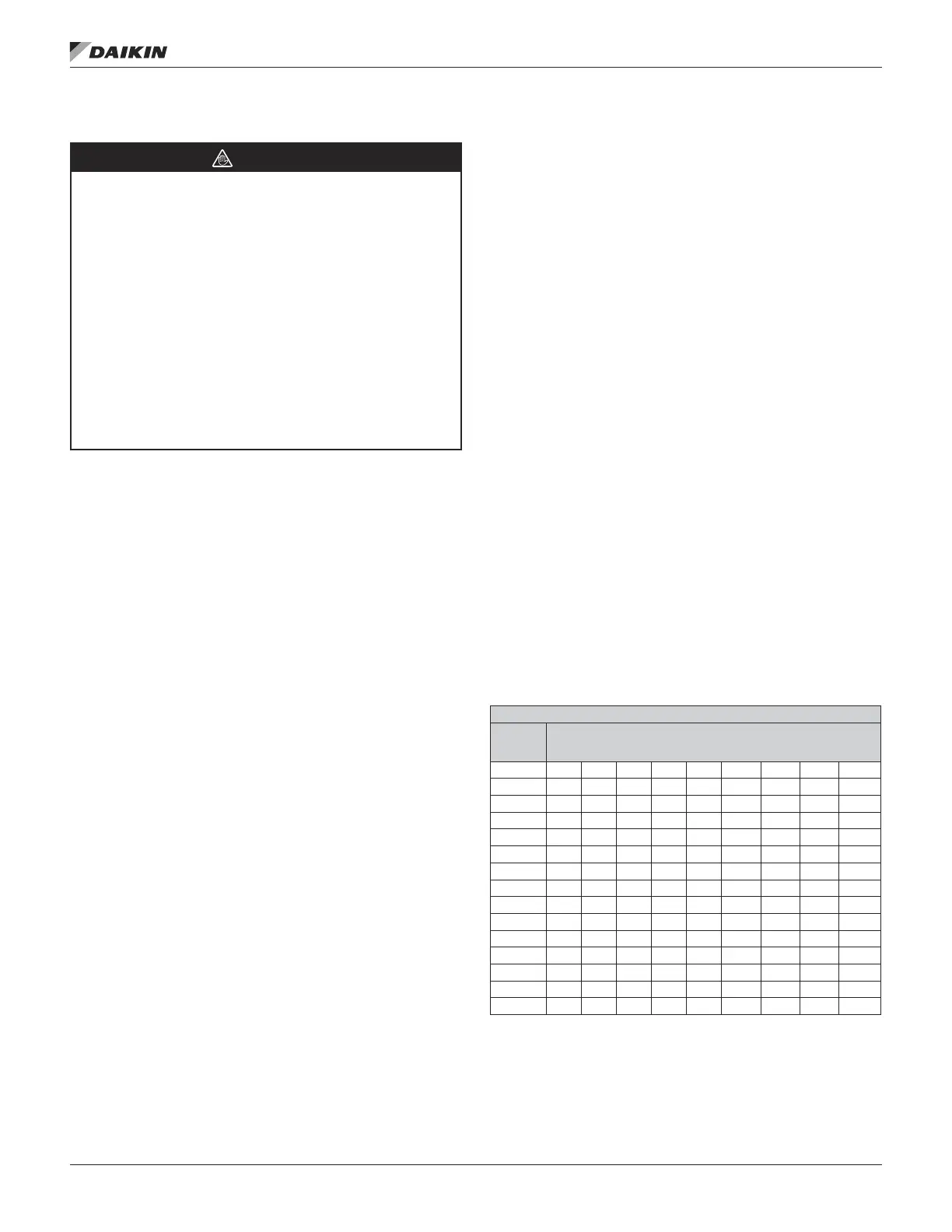
Table 2: Capacity of Pipe Natural Gas (CFH)
WITH PRESSURE DROP OF 0.3" W.C. & SPECIFIC GRAVITY OF 0.60
PIPE
LENGTH
(FT.)
PIPE SIZE-INCHES (IPS)
½ ¾ 1 1¼ 1½ 2 2½ 3 4
10 132 278 520 1050 1600 2050 4800 8500 17500
20 92 190 350 730 1100 2100 3300 5900 12000
30 73 152 285 590 890 1650 2700 4700 9700
40 63 130 245 500 760 1450 2300 4100 8300
50 56 115 215 440 670 1270 2000 3600 7400
60 50 105 195 400 610 1150 1850 3250 6800
70 46 96 180 370 560 1050 1700 3000 6200
80 53 90 170 350 530 990 1600 2800 5800
90 40 84 160 320 490 930 1500 2600 5400
100 38 79 150 305 460 870 1400 2500 5100
125 34 72 130 275 410 780 1250 2200 4500
150 31 64 120 250 380 710 1130 2000 4100
175 28 59 110 225 350 650 1050 1850 3800
200 26 55 100 210 320 610 980 1700 3500
NOTE: Use multipliers in Tables 2 and 3 for other gravities and pressure drops.
IM 684-6 • ROOFTOP SYSTEMS 6 www.DaikinApplied.com
 Loading...


