www.DaikinApplied.com 37 IM 684-6 • ROOFTOP SYSTEMS
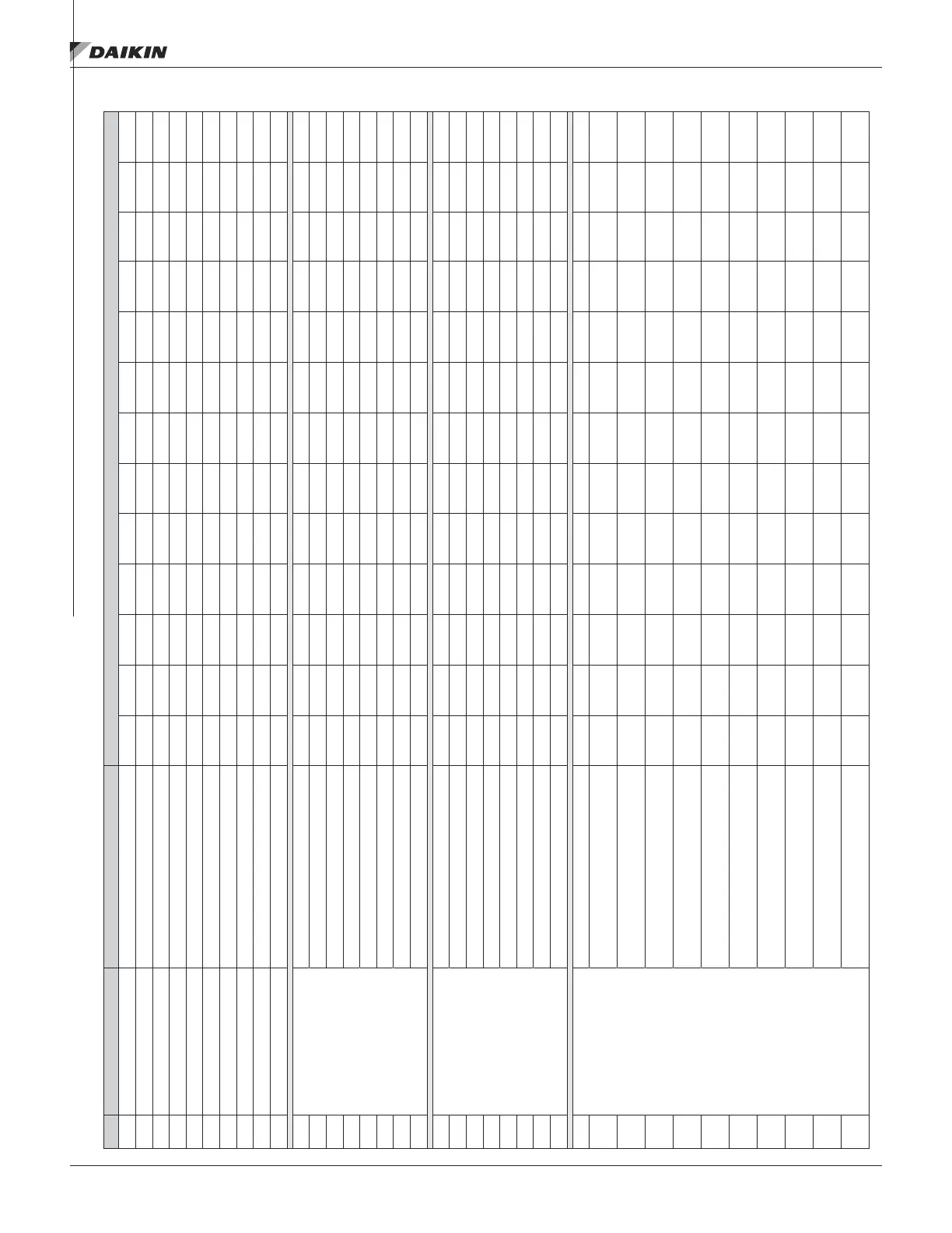
Table 11: Service history
Firing Rate Description of Reading Date of Readings
1 Max. Rate Scale = 100 Gas Manifold Pressure (In. W.C.)*
2 Gas Life Pressure (In. W.C.)*
3 Flame Signal (DC Volts)
4 Ambient Temperature (Deg. F)
5 Flue Gas Temperature (Deg. F)
6 Flue Gas C02 (percent)
7 Flue Gas CO (PPM)
8 Air Pressure in Box (In. W.C.)
9 Burner Motor Volts
10 Burner Motor Amps
11
Mid. Rate
Scale = 50
Gas Manifold Pressure (In. W.C.)*
12 Gas Line Pressure (In. W.C.)*
13 Flame Signal (DC Volts)
14 Ambient Temperature (Deg. F)
15 Flue Gas Temperature (Deg. F)
16 Flue Gas C02 (percent)
17 Flue Gas CO (PPM)
18 Air Pressure in Box (In. W.C.)
19
Min. Rate
Scale = 5
Gas Manifold Pressure (In. W.C.)*
20 Gas Line Pressure (In. W.C.)*
21 Flame Signal (DC Volts)
22 Ambient Temperature (Deg. F)
23 Flue Gas Temperature (Deg. F)
24 Flue Gas C02 (percent)
25 Flue Gas CO (PPM)
26 Air Pressure in Box (In. W.C.)
27
Comments:
(Summarize any service
work performed)
Reference Number (1)
28 (1) Initial Startup of Furnace
*Tap Locations are shown as (2) and (9) on Figure 16.



 To Next Page