General Outline ESIE05-04
1–32 Part 1 – System Outline
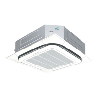
1.16 FUQ71B
Outlook and
dimensions
The illustration below shows the outlook and the dimensions of the unit (mm).
Suspension bolt
Suspension position
Drain
connection
location for
upwards piping
*Drain pipe can
be raised up to 350mm from the top surface of the product.
*When closing the
discharge grill, the
required space is 30mm
or more. (Note 3)
or more*
or more*
or more*
NOTES:
1. Location of unit’s name plate: on bell mouth.
2.In case of using wireless remote controller, this is the position for the
signal receiver. Refer to the drawing of wireless remote controller
for detail.
3. When closing the discharge grill (2 or 3 way discharge), direction of
pipe connecion will be limited, please refer to Installation manual.)
or more*
Height of suspension bracket
or more
(Required space)
Drain
connection
location for rear
piping
Required space
Brand name plate ( Note 2)
 Loading...