Si281312E Procedure to Remove Switch Box
Removal Procedure 7
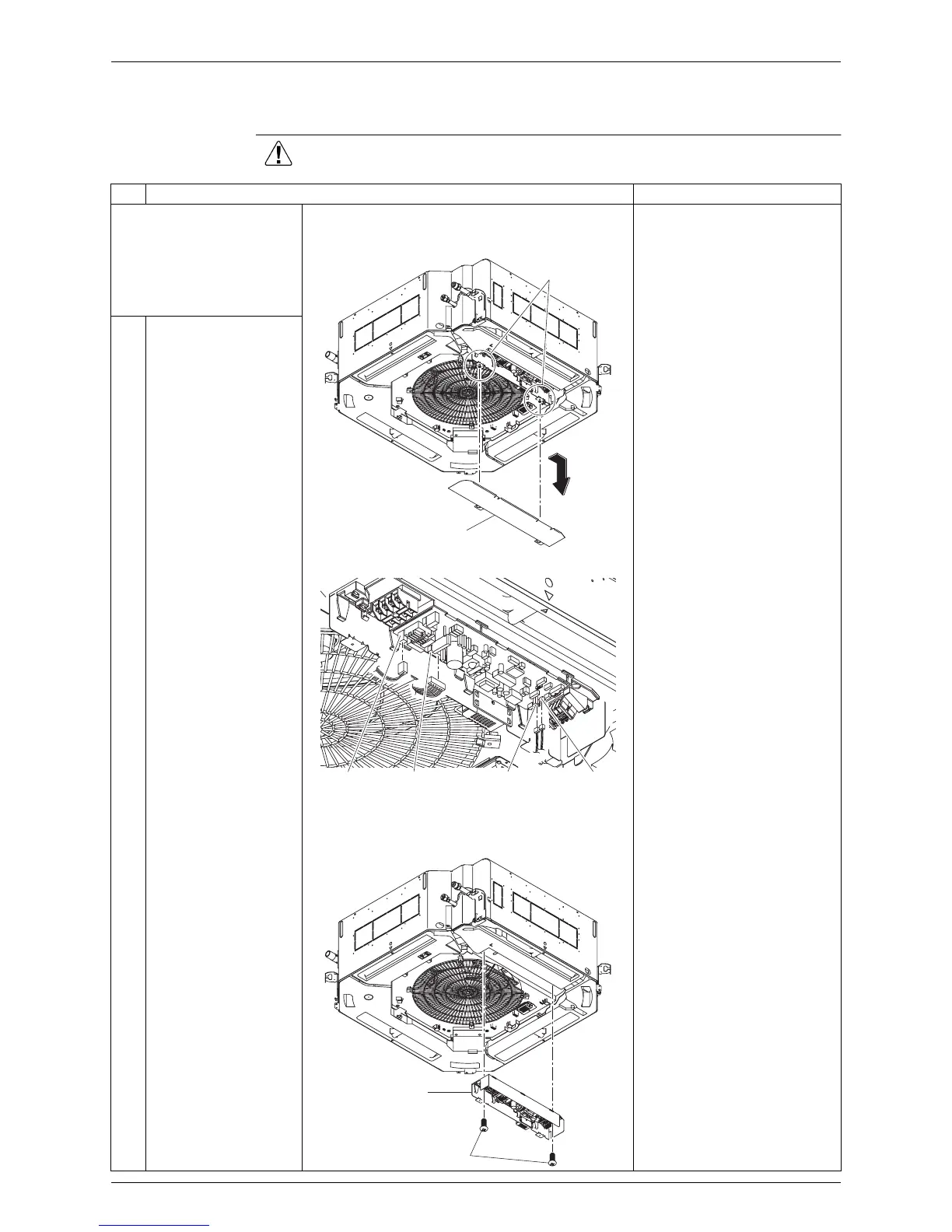
5. Procedure to Remove Switch Box
Procedure Warning Be sure to wait for 10 minutes or more after turning off all power
supplies before disassembling work.
Step
Procedure Points
According to the
procedure for the removal
of decoration panel,
remove the decoration
panel.
1
Unfasten the 2 screws
that fix the lid of the
switch box, and then
slide to remove the lid.
Disconnect every connector
while holding down the tab
beside the connector.
2
Disconnect connectors
shown below from the
inside of the switch box.
·
Flow switch connector
(X15A, white)
·
Heat exchanger
thermistor connector
(X18A, red)
·
Fan motor connector
(X20A, white)
·
Drain pump connector
(X25A, white)
3
Unscrew the 2 screws
that fix the switch box,
and then remove the
switch box.
Fixing screws
Switch box lid
X15AX20AX25A X18A
Fixing screws
Switch box