SiBE121123_A Indoor Unit
Printed Circuit Board Connector Wiring Diagram 40
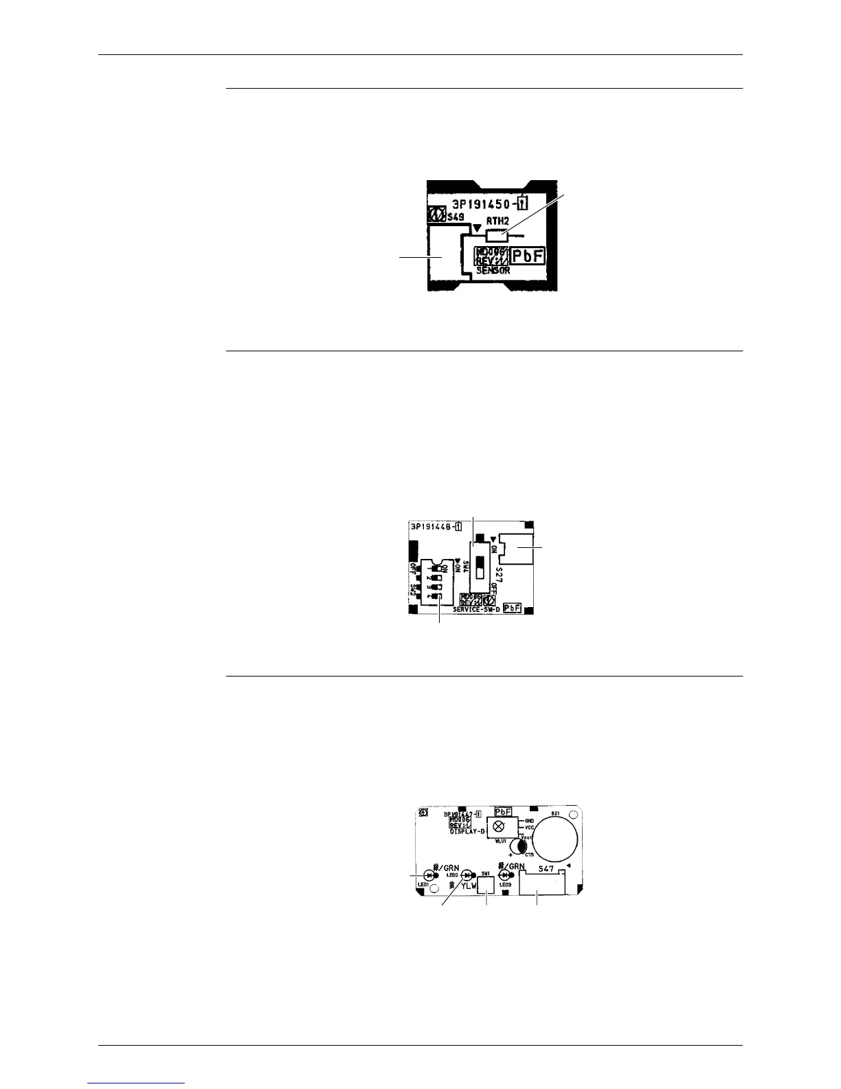
Sensor PCB
Service PCB
Display PCB
LED3 does not function.
1) S49 Connector for control PCB
2) RTH2 (R1T) Room temperature thermistor
S49
RTH2
3P191450-1
1) S27 Connector for control PCB
2) SW2-4 Switch for upward airflow limit setting
∗ Refer to page 230 for detail.
∗ Keep the other switches as factory setting.
3) SW4 (S4W) Switch for airflow selection
∗ Refer to page 57 for detail.
S27
SW4
SW2-4
3P191448-1
1) S47 Connector for control PCB
2) SW1 (S1W) Forced operation [ON/OFF] button
3) LED1 (H1P) LED for operation (green)
4) LED2 (H2P) LED for timer (yellow)
S47SW1LED2
LED1
3P191447-1
 Loading...